
Concrete
Pipe & Precast
Installation
Pocket Guide
ONTARIO CONCRETE PIPE ASSOCIATION
January 2019

Contents
ONTARIO PRODUCER MEMBERS ............................ 1
INTRODUCTION ...................................................... 2
ONTARIO PROVINCIAL STANDARDS ....................... 3
PRECAST CONCRETE PLANT CERTIFICATION ........... 4
PRE-CONSTRUCTION .............................................. 6
SITE PREPARATION ................................................. 6
ORDERING PRECAST CONCRETE PRODUCTS ........... 7
HANDLING .............................................................. 8
Load-Carrying Capacity of Lift Anchors ................. 9
Handling Pipe ...................................................... 10
900 mm Diameter and Smaller ........................ 10
975 mm Diameter and Larger .......................... 10
Handling MH Sections ......................................... 11
Handling Box Units .............................................. 13
JOB SITE PRODUCT RECEIVING ............................. 15
Inspection of Product Shipment .......................... 15
Unloading ............................................................ 16
Stockpiling ........................................................... 16
Storage ................................................................ 17
EXCAVATIONS ...................................................... 19
Excavated Material .............................................. 20
Dewatering .......................................................... 21
Support Systems .................................................. 21
Trench Boxes .................................................... 22
CONCRETE PIPE INSTALLATION ............................. 24
Pipe Details .......................................................... 24
Wall Thickness ..................................................... 26
Excavation Limits ................................................. 26
Line and Grade .................................................... 28
Foundation Preparation ...................................... 32
Pipe Bedding ........................................................ 33
Bedding Materials ............................................ 35
Class B Bedding ................................................ 36
Class C Bedding ................................................ 36
Cover ................................................................... 36
Backfill ................................................................. 37
Jointing ................................................................ 39
Jointing Materials ................................................ 39
Rubber Gaskets ................................................ 40
Mastic .............................................................. 41
Mortar .............................................................. 42
External Bands ..................................................... 42
Jointing Procedures ............................................. 44
Jointing Procedures for Pre-lubricated Gasket
with Single Offset Joints ................................... 47
Jointing Procedures for O-Ring Gasket ............ 50
How to Use Lift Anchors for Setting Pipe ......... 54
Service Connections ............................................ 56
Changes in Alignment .......................................... 56
MH INSTALLATION ............................................... 58
Prebenched MH Monobases ............................... 59
MH Connections .................................................. 59
Precast Concrete Adjustment Units .................... 61
Frames with Grates or Covers ............................. 61
BOX UNIT INSTALLATION ...................................... 62
Foundations ......................................................... 62
Bedding ............................................................... 63
Levelling ............................................................... 63
Backfill and Cover ................................................ 63
Distribution Slab .................................................. 64
FIELD TESTING ...................................................... 64
Soil Density .......................................................... 65
Visual/Video Inspection....................................... 66
Infiltration Testing ............................................... 67
Exfiltration Testing .............................................. 68
Testing With Water .......................................... 68
Low Pressure Air Testing .................................. 70
Leakage Test Acceptance .................................... 70
APPENDIX ............................................................. 71
APPENDIX A – Concrete Jacking Pipe .................. 72
APPENDIX B – Damage Assessment .................... 76
Repair Types .................................................... 76
Joint Integrity ................................................... 77
Cracks ............................................................... 79
Basis of Acceptance ......................................... 84
Autogenous Healing ............................................ 85
Rehabilitation Techniques ................................... 86
Chemical Grout ................................................ 87
Trenchless Technologies .................................. 88
REFERENCES ......................................................... 90

Concrete Pipe & Precast Installation
1
ONTARIO PRODUCER MEMBERS
Coldstream Concrete
402 Quaker Lane, RR#2
Ilderton, ON N0M 2A0
(519) 666-0604
coldstreamconcrete.com
Con Cast Pipe
299 Brock Road South
Puslinch, ON N0B 2J0
1-800-668-7473
concastpipe.com
DECAST Ltd
8807 County Road 56
Utopia, ON L0M 1T0
1-800-461-5632
decastltd.com
Forterra Pipe & Precast
2099 Roseville Road
Cambridge, ON N1R 5S3
1-888-888-3222
forterrabp.com
M CON Pipe & Products
2691 Greenfield Road
Ayr, ON N0B 1E0
1-866-537-3338
mconproducts.com
M CON Products
2150 Richardson Side Road
Carp, ON K0A 1L0
1-800-267-5515
mconproducts.com
Miller Precast
58 Cooper Road
Rosslyn, ON P7K 0E3
(807) 939-2655
millerprecast.ca
Rainbow Concrete Industries
2477 Maley Drive
Sudbury, ON P3A 4R7
1-800-461-6281
rcil.ca

Concrete Pipe & Precast Installation
2
INTRODUCTION
Proper installation is a critical step in a process that also
includes surface and sub-surface investigations, detailed
design, specification preparation, quality manufacturing,
and field testing.
The design of a concrete pipeline assumes that certain
minimum conditions of installation will be met in the field.
Acceptance criteria should be established by the owner to
ensure that the quality of workmanship and materials
provided during construction has met the design
requirements.
Standard specifications for the installation of precast
concrete drainage products can also be found in the
following references:
Product
OPSS
ASTM
Concrete Pipe
410
C1479
MH and CB
407
C1821
Box
422
C1675
General installation procedures are presented in this
guide, together with some of the problems that might be
encountered. This is only a guide and is not intended to
supersede the project specifications.

Concrete Pipe & Precast Installation
3
ONTARIO PROVINCIAL STANDARDS
The Ontario Provincial Standards (OPS) for Roads and
Public Works were published for the first time in January
1984, with the intent of improving the administration and
cost-effectiveness of road building and other municipal
services, such as sewers and watermains. OPS drawings
and specifications correspond to those used by many
municipalities and the Ontario Ministry of Transportation.
The Ontario Provincial Standards currently contain the
following manuals:
Ontario Provincial Standards Specifications (OPSS)
Ontario Provincial Standards Drawings (OPSD)
An online version of these standards can be found at:
www.ops.on.ca
Relevant OPS documents are listed in some sections of this
guide for easy reference.

Concrete Pipe & Precast Installation
4
PRECAST CONCRETE PLANT CERTIFICATION
As of January 1, 2018, the Canadian Precast/Prestressed
Concrete Institute (CPCI) and the Canadian Concrete Pipe
and Precast Association (CCPPA) established an
independent third-party administered and audited
certification program for both prestressed and non-
prestressed precast concrete manufacturing facilities
across Canada.
Both the CPCI and CCPPA recognize the mutual benefit for
owners, contractors, and the precast concrete industry by
combining the strengths of two well-established national
plant certification programs, CPCI Certification Program for
Structural, Architectural and Specialty Products and
Production Processes (CPCI Certification) and the Plant
Prequalification Program for Precast Concrete Drainage
Products (PPP), into the new Canadian Precast Concrete
Quality Assurance (CPCQA) Certification Program.

Concrete Pipe & Precast Installation
5
In Ontario, manufacturers of precast concrete drainage
products must possess a current Prequalification
Certificate in accordance with the Ontario Provincial
Standard Specifications listed below:
OPSS 1351
Precast Reinforced Concrete Components for MH,
Catch Basins, Ditch Inlets, and Valve Chambers
OPSS 1820 Circular and Elliptical Concrete Pipe
OPSS 1821
Precast Reinforced Concrete Box Culverts and Box
Sewers
Plants that are prequalified must identify all precast
concrete drainage products covered by their certification,
with this marking:
For a list of prequalified plants or more information about
the precast concrete certification program visit:
www.precastcertification.ca
.

Concrete Pipe & Precast Installation
6
PRE-CONSTRUCTION
Pre-construction planning is essential for a successful
project. All engineering plans, project specifications, soils
reports, standard drawings, and special provisions must be
reviewed prior to construction. A review of the design at
the project site is helpful in identifying potential problems.
Addressing these potential problems can eliminate
unnecessary and costly delays.
All personnel associated with the project should become
familiar with the federal, provincial and local occupational
health and safety codes related to construction projects.
SITE PREPARATION
Site preparation can significantly influence progress of the
project. The amount and type of work involved in site
preparation varies with the location of the project,
topography, surface conditions, and existing utilities.
References in Ontario Provincial Standards:
OPSS 490
Site Preparation for Pipelines, Utilities, and
Associated Structures
OPSS 491
Preservation, Protection, and Reconstruction of
Existing Facilities
OPSS 510
Removal

Concrete Pipe & Precast Installation
7
ORDERING PRECAST CONCRETE PRODUCTS
The ordering of materials is the contractor’s responsibility,
however design engineer and supplier familiarity with the
contractor’s proposed schedule will enable better
coordination to avoid delays in product deliveries and
avoid unnecessary product handling.
Precast concrete manufacturers stock a wide range of
standard components, however longer delivery lead times
may be required when large quantities and/or custom
precast concrete products are required. Information
required to initiate an order should include:
Name and location of project
Design and manufacturing standards
Product size, type, strength class, and quantities
Joint materials or performance requirements
List of special fittings
Product or material test requirements
Delivery date
Invoicing instructions
The contractor must provide access roads to allow delivery
trucks to reach the unloading area under their own power.
References in Ontario Provincial Standards:
OPSS 1351
Precast Reinforced Concrete Components for MH,
Catch Basins, Ditch Inlets, and Valve Chambers
OPSS 1820
Circular and Elliptical Concrete Pipe
OPSS 1821
Precast Reinforced Concrete Box Culverts and Box
Sewers

Concrete Pipe & Precast Installation
8
HANDLING
IMPORTANT
Work procedures for material handling, worker safety,
the modification of excavators for use as cranes, and all
components of any lifting assembly for precast concrete
products must comply with the Occupational Health and
Safety Act requirements for Construction Projects
(Ontario Regulation 213/91). A competent person
designated by the contractor should inspect all lifting
assemblies and attachment hardware prior to each use.
Any damage or defective lifting equipment must be
immediately removed from service. All other safety
procedures and recommended operating practices by the
manufacturer of commercial lifting equipment must be
followed. Failure to observe the above warnings may
lead to property damage, personnel injury and death.
All precast concrete products must be handled with
reasonable care. The Contractor must take all necessary
precautions to ensure the method used in lifting or placing
the product uniformly distributes the weight and does not
induce point loading on the product.
Proprietary lifting systems are typically used for precast
concrete products, including pipe, box units, and
maintenance hole components. It is imperative that all
lifting system components and rigging hardware be used
as they are intended.

Concrete Pipe & Precast Installation
9
Load-Carrying Capacity of Lift Anchors
IMPORTANT
Lift anchors are sized and located specifically for each
precast concrete product to be lifted individually.
Contractors must not attempt to lift more than one
precast concrete section at a time, and must ensure that
the load is applied to all lift anchors simultaneously in
order to safely lift the product.
The MAXIMUM safe working load is clearly visible on the
head of the lift anchor for easy recognition of the
appropriate hardware and accessories to be used.
However the safe working load of any lift anchor may be
significantly reduced due to several factors, such as:
Length of anchor, or embedment depth
Distance to edges, corners or openings
Concrete compressive strength
Number of lifting points and type of rigging used
Direction of pull (cable or sling angle)
Impact or dynamic loads

Concrete Pipe & Precast Installation
10
Handling Pipe
900 mm Diameter and Smaller
Lifting devices such as slings, chains or cables should be
placed around the pipe, or arranged so that the pipe is
lifted in a horizontal position at all times. If the lifting
device could chip or damage the pipe, padding should be
provided between the pipe and lifting device. These types
of lifting devices should not be passed through the pipe.
A common device used for unloading small to
intermediate diameter pipe (900 mm and smaller), is a lift
fork. Lift forks are easily attached to a heavy equipment
machine, such as a front end loader. Lift forks make
unloading more efficient, and enable the contractor to
easily move pipe around the site.
975 mm Diameter and Larger
Concrete pipe 975 mm and larger are typically provided
with two embedded lift anchors placed laterally along the
top of the pipe. Special pipe fittings may require more
than two lift anchors in various other locations on the

Concrete Pipe & Precast Installation
11
product. Because the pipe is lifted by two or more points,
stability during lifting is established.
When pipe is provided with lift holes, the lifting device
should pass through the wall and distribute the weight
along the inside barrel of pipe. Concrete pipe with lift
holes, require a specially designed lifting device consisting
of a steel thread eye bar with a wing type nut and bearing
plate. Lift holes should be filled in after the pipe is
installed.
Handling MH Sections
In maintenance hole products, lift anchors are typically
placed on the sides of the product. MH components have

Concrete Pipe & Precast Installation
12
one or more lift anchors on either side of the product for
stability during installation and stacking.
For MH sections provided with lift holes, properly
designed and sized lifting pins should be used.

Concrete Pipe & Precast Installation
13
Using short lifting cables or chains that result in a sling
angle greater than 60 degrees can greatly increase the
possibility of damaging the top shoulders of the MH riser
and potentially cause the MH riser to fail structurally.
When MH risers have multiple hole openings, extra care
must be taken to reduce the inward force from the rigging
by means such as a spreader beam or longer cables.
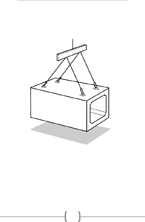
Handling Box Units
Concrete box units are typically provided with four
embedded lift anchors placed on the top slab. Additional
lift anchors may be provided for unloading, or rotating the
product from its shipping position to its installed position.
Concrete Pipe & Precast Installation
14
Special box fittings may require lift anchors in various
other locations on the product. Because the box is lifted
by two or more points, stability during lifting is
established.
Source: Guidelines for Handling Concrete Pipe and Utility
Products by Dayton Superior.

Concrete Pipe & Precast Installation
15
JOB SITE PRODUCT RECEIVING
Inspection of Product Shipment
Each shipment of precast concrete product is blocked and
tied down at the plant to avoid damage during transit. The
product should be inspected on the truck when it first
arrives at the jobsite before it is unloaded to ensure that
damage has not occurred during transit. Damaged or
missing items must be reported at this time.
It is important to check that the product is the correct size,
type, and strength class, and is supplied with the proper
joint material. Typically markings on the product include:
Manufacturing standard
Strength designation, such as pipe class or design
earth cover
Date of manufacture
Name or trademark of the manufacturer
Quality assurance program certification, if applicable
Appropriate markings to indicate the correct
orientation when installed, if applicable
Other markings as specified by the owner

Concrete Pipe & Precast Installation
16
Unloading
Unloading of precast concrete product should be done on
a level site and be controlled to avoid colliding with other
products. Care should be taken to avoid damage,
especially to the bells and spigots. Caution should be
exercised to ensure personnel are out of the path of the
product as it is moved.
If the product is damaged during delivery or unloading, the
product should be set aside. Minor chips or cracks which
do not pass through the wall can usually be repaired. The
manufacturer can provide advice on proper repair
methods.
If the product has to be moved after unloading, the
sections should be lifted, and should never be dragged.
Transporting product over rough ground should be done in
a manner that prevents excessive impact or dynamic loads
on the lifting hardware. Pipe sections should not be rolled
over rough ground.
Stockpiling
If the excavation is open, the pipe should be placed on the
side opposite the excavated material. The pipe sections
should be placed so that they are protected from traffic
and construction equipment, but close enough to the
trench edge to minimize handling.
If the excavation is not yet open, the pipe should be strung
out on the opposite side from where the excavated
material will be placed. To avoid disruption to existing

Concrete Pipe & Precast Installation
17
natural drainage and enable construction to proceed as
quickly as possible, pipe installation should follow
immediately after preparation of the bedding foundation.
For culverts to be installed on shallow bedding at
approximately the same elevation as original ground, the
pipe should be strung out immediately after clearing and
rough grading.
Storage
Storage of pipe should be as close as is safely possible to
where the pipe will be installed. Pipe sections generally
should not be stored at the job site in a greater number of
layers that would result in a total height of 2 m.
Pipe should be layered in the same manner as they were
loaded on the truck. Pipe should be placed on timbers to
prevent them from becoming frozen to the ground in the
winter, and to permit ease of handling in summer. For
small diameter pipe sizes that have protruding bells, the
pipe barrel should carry the weight of the pipe keeping the
bell ends free of load concentrations.
The bottom layer should be placed on a level base, on
timbers supporting the barrel at either end. Each layer of
bell and spigot pipe should be arranged so that bells are at
the same end. The bells in the next layer should be at the
opposite end, and projecting beyond the spigot of the
section in the lower layer. Where only one layer is being
stockpiled, the bell and spigot ends should alternate
between adjacent pipe sections.

Concrete Pipe & Precast Installation
18
All flexible gasket materials, including joint lubricating
compounds where applicable should be stored in a cool
dry place in the summer, and prevented from freezing in
the winter. Rubber gaskets and preformed mastics should
be kept clean, away from oil, grease, excessive heat, and
out of direct sunlight.

Concrete Pipe & Precast Installation
19
EXCAVATIONS
For sewer and culvert construction, the scope of
operations involved in general includes excavating, soil
stabilization, backfilling, and control of groundwater and
surface drainage.
Adequate knowledge of subsurface conditions is essential
for any type of excavation. This is accomplished through
soil surveys and subsequent soil classification. Soil borings
are usually obtained for design purposes, and the
information included on the plans, or made available to
the contractor in a geotechnical report. This soil boring
information is useful in evaluating unsuitable subsoil
conditions requiring special construction. If the subsoil
information on the plans is not sufficiently extensive, it is
normally the responsibility of the contractor to obtain
additional test borings.
It is the contractor’s responsibility to adhere to all
Occupational Health and Safety Act requirements for
excavations. The sloping requirements for Soil Type 1, 2, 3
or 4 are described in OHSA Ontario Regulation 213/91 for
Construction Projects and is detailed in the OPSD 802.03X
and 802.05X series drawings for concrete pipe installation.
References in Ontario Provincial Standards:
OPSS 401
Trenching, Backfilling, and Compacting
OPSS 403
Rock Excavation for Pipelines, Utilities, and
Associated Structures in Open Cut
OPSS 539
Temporary Protection Systems
OPSS 902
Excavating and Backfilling – Structures

Concrete Pipe & Precast Installation
20
Excavated Material
In open cut installations, suitable excavated material is
usually used for backfill, and should be placed in a manner
that reduces re-handling during backfilling operations.
Stockpiling excavated material adjacent to the trench
causes a surcharge load which may cave in trench walls.
The ability of the trench walls to stand vertically under this
additional load depends on the cohesion characteristics of
the particular type of material being excavated. This
surcharge load should be considered when evaluating the
need to provide trench support. As a general rule, for
unsupported trenches, the minimum distance from the
trench to the toe of the spoil bank should not be less than
one half the trench depth. For supported trenches, a
minimum of 1.0 m is normally sufficient.
For deep or wide excavations, it may be necessary to haul
away a portion of the excavated soil or spread the
stockpile with a bulldozer or other equipment.
If the excavated soil differs significantly from the backfilled
material set forth in the plans, it may be necessary to haul
the unsuitable soil away and import backfill material. All
material to be used as backfill should be visually inspected
for frozen lumps, cinders, ashes, refuse, vegetable or
organic matter, rocks and boulders over 150 mm in any
dimension, and other deleterious material.

Concrete Pipe & Precast Installation
21
Dewatering
A continuous dewatering operation should be provided in
order to keep the excavation stable and free of water.
Dewatering efforts must be monitored for impacts to
items such as ground settlement and ground water usage.
Water from dewatering operations must be disposed of in
accordance with local regulations. Pumped water requires
that it be filtered through a sediment control measure and
disposed of such that it does not cause erosion or other
damage to adjacent lands.
When dewatering efforts are no longer required they must
be discontinued in a manner so that disturbance of any
structure or pipeline is avoided.
References in Ontario Provincial Standards:
OPSS 517
Dewatering of Pipeline, Utility, and Associated
Structure Excavation
OPSS 518
Control of Water from Dewatering Operations
Support Systems
Soil stabilization may require the opinion of a professional
engineer to ensure that the walls of an excavation are
sufficiently stable before any workers enter the
excavation. The support system requirements for
excavations in Soil Type 1, 2, 3 or 4 are described in OHSA
Ontario Regulation 213/91 for Construction Projects.

Concrete Pipe & Precast Installation
22
The structural requirements of a support systems depend
on numerous factors such as:
depth and width of excavation
characteristics of the soil
water content of the soil
weather conditions
proximity to other structures
vibration from construction equipment or traffic
soil placement or other surcharge loads
code requirements
As the excavation is backfilled, the support system should
be removed, unless it is specified to be left in place.
Improper removal of a support system can affect the
backfill load on the pipe or structure, so it should be
withdrawn gradually as backfilling progresses. Additional
compaction of the backfill material may be necessary to fill
the voids behind the support system, as it is removed. The
procedure for extracting the support system and placing
backfill shall ensure the backfill load is applied gradually
and disturbance of the pipeline or structure is avoided.
Trench Boxes
Trench boxes, or shields, are prefabricated support
systems composed of heavily braced steel sidewalls, and
are capable of being moved as a unit to protect workers as
pipe installation progresses. Trench boxes are commonly
used for pipe or box installations and must be designed by

Concrete Pipe & Precast Installation
23
a professional engineer in accordance with OHSA Ontario
Regulation 213/91 for Construction Projects.
When a trench box is used, care should be taken when the
shield is moved ahead, so as not to disturb the bedding or
pull the pipe or box joints apart.
Specially designed manhole shields are also available for
the installation of maintenance holes, or other vertical
structures.
References in Ontario Provincial Standards:
OPSS 404
Support Systems
OPSS 539
Temporary Protection Systems

Concrete Pipe & Precast Installation
24
CONCRETE PIPE INSTALLATION
This section covers the requirements for the installation of
concrete pipe in open cut. Pipe installation using
trenchless methods are discussed in Appendix A.
References in Ontario Provincial Standards:
OPSS 401
Trenching, Backfilling, and Compacting
OPSS 403
Rock Excavation for Pipelines, Utilities, and
Associated Structures in Open Cut
OPSS 410
Pipe Sewer Installation in Open Cut
OPSS 421
Pipe Culvert Installation in Open Cut
Pipe Details
Cross-section

Concrete Pipe & Precast Installation
25
Expanded Bell End - 975mm Dia & Smaller
Flush Bell End - 1050mm Dia & Larger

Concrete Pipe & Precast Installation
26
Wall Thickness
Concrete pipe is typically supplied with industry standard
wall thicknesses, but may vary by manufacturer. Wall
thickness can be determined with the following equations:
: t =
ID
12
: t =
ID
12
+ 1
: t =
ID
12
+ 1.75
Where: t = wall thickness (inches)
ID = inside pipe diameter (inches)
Excavation Limits
The most important excavation limitations are trench
width and depth. As excavation progresses, trench grades
should be periodically checked against the elevations
established on the sewer profile.
Improper trench depths can result in high or low spots in
the line, which may adversely affect the hydraulic capacity
of the sewer, and require correction or additional
maintenance after the line is completed. If the trench
depth is excavated beyond the limits of the required
excavation, granular material should be placed and
compacted in the trench to reinstate the required trench
limits prior to backfilling the trench.

Concrete Pipe & Precast Installation
27
The backfill load transmitted to the pipe is directly
dependent on the trench width at the crown of the pipe.
To determine the backfill load the designer assumes a
certain trench width, and then selects a pipe strength
capable of withstanding this load. If the constructed
trench width exceeds the maximum trench width specified
in the design, the pipe may be overloaded and may require
the use of a stronger pipe or a higher class of bedding, or
both. Where maximum trench widths are not indicated in
any of the construction contract documents, trench widths
should be as narrow as possible, with side clearance
adequate enough to ensure proper compaction of backfill
material at the sides of the pipe.
When unstable soil conditions are encountered, sheathing
or shoring can be used, or the banks of the trench can be
sloped to the natural angle of repose of the native soil. If
the trench sides are allowed to slope back, the pipe should
be installed in a shallow subtrench excavated at the
bottom of the wider trench. The depth of the subtrench
should be at least equal to the vertical height of the pipe.
For a confined trench installation, OPSD 802.03X specifies
the following trench widths at the top of the pipe:
SIDE CLEARANCE TABLE
Pipe Inside Diameter
(mm)
Side Clearance
(mm)
900 or less
300
Over 900
500

Concrete Pipe & Precast Installation
28
For culverts installed under embankments, it may be
possible to simulate a narrow subtrench by installing the
pipe in the existing stream bed.
When culverts are installed in a negative projecting
condition of construction, the same excavation limitations
should be followed as for trench excavation.
OPSS 401 requires that no more than 15 m of trench be
open in advance of the completed pipe system.
References in Ontario Provincial Standards:
OPSS 401
Trenching, Backfilling, and Compacting
Line and Grade
For sewer construction, where the pipe is installed in a
trench, line and grade are usually established by one, or a
combination of the following methods:
Control points consisting of stakes and spikes set at
the ground surface, and offset a certain distance from
the proposed sewer centerline
Control points established at the trench bottom, after
the trench is excavated
Trench bottom and pipe invert elevations established
while excavation and pipe installation progresses
Global Positioning System (GPS)

Concrete Pipe & Precast Installation
29
IMPORTANT
Line and grade should be checked as the pipe is installed,
and any discrepancies between the design and actual
alignment and pipe invert elevations should be corrected
prior to placing the backfill or fill over the pipe.
Where control points are established at the surface and
offset, lasers, transits, batter boards, tape and level, or
specially designed transfer instruments, are used to
transfer line and grade to the trench bottom. Regardless
of the specific type of transfer apparatus used, the basic
steps are:
Stakes and spikes, as control points, are driven flush
with the ground surface at 7.5 to 15m intervals for
straight alignment, with shorter intervals for curved
alignment.
Offset the control points 3m, or another convenient
distance, on the opposite side of the trench from
which excavated material will be placed.
Determine control point elevations by means of a
level, transit or other leveling device. Drive a guard
stake to the control point, and mark the depth of the
control point from the control point to the trench
bottom or pipe invert.
After the surface control points are set, a grade sheet
is prepared listing reference points, stationing, offset
distance and vertical distance from the control points
to the trench bottom or pipe invert.

Concrete Pipe & Precast Installation
30
Transferring the line and grade along the trench bottom is
achieved by using a laser system, or a batter board system.
The laser system, the most commonly used system, uses a
transit or level to set the starting point on the trench
bottom. As with any surveying instrument, the initial
setting is most important. Once the starting point is
established, the laser can be set for direction and grade.
Temperature can affect the trueness of the laser beam;
therefore, it is helpful to keep the line well ventilated. The
laser instrument can be mounted in a maintenance hole,
set on a tripod or placed on a solid surface to project the
light beam either inside, or outside the pipe.
There are two types of batter board systems. One type is
incorporated for narrow trenches, the other for wide
trenches.
For narrow trenches, a horizontal batter board is spanned
across the trench, and adequately supported at each end.
The batter board is set level at the same elevation as the
stringline, and a nail driven in the upper edge, at the
centerline of the pipe. In many cases the batter board is
used only as a spanning member, with a short vertical
board nailed to it at the pipe centerline. A stringline is
pulled tight across a minimum of three batter boards, and
the line transferred to the bottom by a plumb bob cord
held against the stringline. Grade is transferred to the
trench bottom by means of a grade rod, or other suitable
vertical measuring device.

Concrete Pipe & Precast Installation
31
Example Batter Board Set-up for Narrow Trench
Where wide trenches are necessary, due to large pipe sizes
or sloped trench walls, the batter board may not be able
to span the width of excavation. In such cases, the same
transfer principle is used, except that the vertical grade
rod is attached to one end of the batter board, and the
other end set level against the offset stringline. The length
of horizontal batter board is the same as the offset
distance. The length of the vertical grade rod is the same
as the distance between the pipe invert and the stringline.

Concrete Pipe & Precast Installation
32
Foundation Preparation
A stable and uniform foundation is necessary for
satisfactory performance of any pipe. The foundation
must have sufficient load bearing capacity to maintain the
pipe in proper alignment and support the loads of the
backfill material placed over the pipe. The foundation
should be checked for hard or soft spots, due to rocks or
low load-bearing soils. Where undesirable foundation
materials exist, it should be stabilized by ballasting, or soil
modification.
Ballasting requires removal of the undesirable foundation
material and replacing it with select materials such as
sand, gravel, crushed rock, slag, or suitable earth backfill.
The depth, gradation, and size of the ballast depend on
the specific material used and the amount of stabilization
required, but usually the ballast should be well graded.
Soil modification involves the addition of select material to
the native soil. Crushed rock, gravel, sand, slag, or other
durable inert materials with a maximum size of 75 mm, is
worked into the subsoil to the extent necessary to
accomplish the required stabilization.
In rock or hard, unyielding soils, the excavation should be
continued below grade, and the over-excavation replaced
with select material to provide a cushion for the pipe.
References in Ontario Provincial Standards:
OPSS 401
Trenching, Backfilling, and Compacting

Concrete Pipe & Precast Installation
33
Pipe Bedding
Once a stable and uniform foundation is provided, it is
necessary to prepare a bedding in accordance with the
requirements set forth in the plans, specifications or
standard drawings.
An important function of the bedding is to level out any
irregularities in the foundation, and assure uniform
support along the barrel of each pipe section. The bedding
is also constructed to distribute the load bearing reaction,
due to the mass of the backfill or fill material, around the
lower periphery of the pipe. The structural capacity of the
pipe is directly related to this load distribution, and several

Concrete Pipe & Precast Installation
34
types of bedding have been established to enable the
specification of pipe strengths during the design phase.
This guide describes the Class B and Class C Beddings since
these are commonly used in the Ontario Provincial
Standards for rigid pipe. Other bedding types, such as
Standard Installations Types 1 to 4, are described in the
OCPA Concrete Pipe Design Manual and the Canadian
Highway Bridge Design Code (CSA S6).
The following general requirements should be understood:
Bedding material placed in the haunches must be
compacted prior to continued placement of cover
material. To ensure support in the haunches, the
bedding under the middle third of the pipe should be
loosely placed and uncompacted.
Bedding material should be placed in layers not
exceeding 200 mm in thickness, loose measurement,
and compacted to contract specifications before a
subsequent layer is placed.
Bedding on each side of the pipe should be
completed simultaneously. At no time should the
levels on each side differ by more than the 200 mm
uncompacted layer.
Bell holes should be excavated to accommodate
projecting joints, and to provide support along the
barrel of the pipe.

Concrete Pipe & Precast Installation
35
Uniform Support for Pipe with Expanded Bells
References in Ontario Provincial Standards:
OPSS 401
Trenching, Backfilling, and Compacting
OPSS 501
Compacting
OPSD
802.030 to
802.034
Rigid Pipe Bedding, Cover, and Backfill Drawings
OPSD
802.050 to
802.054
Horizontal Elliptical Rigid Pipe Bedding, Cover, and
Backfill Drawings
Bedding Materials
Materials for bedding should be selected on the basis that
uniform contact can be obtained between the bedding and
the pipe. Since most granular material will shift to attain
this uniform contact as the pipe settles, an ideal load
distribution can be realized.
OPSS 401 specifies that bedding material be:
Granular A
Granular B, Type I, II, or III, 26.5 mm or less in
size, or
Unshrinkable fill in accordance with OPSS 1359.

Concrete Pipe & Precast Installation
36
Class B Bedding
The bedding depth below the pipe has a specified
thickness of 0.15 times the outside pipe diameter,
with a minimum of 150mm and maximum of 300mm.
Class B Bedding should extend at least half way up at
the sides of the pipe (to springline).
The bedding material is shaped to receive the bottom
of the pipe. The width should be sufficient to allow
0.6 times the outside pipe diameter for circular pipe,
and 0.7 times the outside span for elliptical pipe.
Class C Bedding
The bedding depth below the pipe has a specified
thickness of 0.15 times the outside pipe diameter,
with a minimum of 150mm and maximum of 300mm.
Class C Bedding should extend up the sides of the
pipe for a height of at least 0.15 times the outside
pipe diameter (forming a 90 degree bedding angle).
The bedding material is shaped to receive the bottom
of the pipe. The width should be sufficient to allow
0.5 times the outside pipe diameter for circular pipe,
and 0.5 times the outside span for elliptical pipe.
Cover
Cover material should be placed so that damage to or
movement of the pipe is avoided.
OPSS 401 specifies that cover material be:
Granular A, or

Concrete Pipe & Precast Installation
37
Granular B, Type I, II, or III, 26.5 mm or less in
size
The following general requirements should be understood:
Compacted cover material should be placed on top of
the bedding to a depth of at least 300 mm above the
top of the pipe.
Cover material should be placed in layers not
exceeding 200 mm in thickness, loose measurement,
and compacted to contract specifications before a
subsequent layer is placed.
Cover on each side of the pipe should be completed
simultaneously. At no time should the levels on each
side differ by more than the 200 mm uncompacted
layer.
Heavy equipment should not be used for compacting until
there is a minimum depth of 900mm above the crown of
the pipe.
Backfill
OPSS 401 specifies that backfill material be:
Granular A
Granular B, Type I, II, or III
Unshrinkable fill in accordance with OPSS 1359
Approved native material
The following general requirements should be understood:

Concrete Pipe & Precast Installation
38
Backfill material should be placed in uniform layers
not exceeding 300 mm in thickness for the full width
of the trench and each layer should be compacted to
95% of the maximum dry density before a subsequent
layer is placed.
Backfill should be placed to a minimum depth of
900mm above the crown of the pipe before power
operated tractors or rolling equipment should be
used for compacting. Uniform layers of backfill
material exceeding 300mm in thickness may be
placed with the approval of the Contract
Administrator.
If the contract specifies native backfill material,
acceptable earth backfill material may be substituted
with the approval of the Contract Administrator. In
areas within the roadway, for a depth equal to the
frost treatment, the earth backfill material should
have frost susceptible characteristics similar to the
adjacent material.
References in Ontario Provincial Standards:
OPSS 401
Trenching, Backfilling, and Compacting
OPSS 492
Site Restoration Following Installation of Pipelines,
Utilities, and Associated Structures
OPSS 501
Compacting

Concrete Pipe & Precast Installation
39
Jointing
Pipe should be lowered into the trench, or set in place for
embankment installations, with the same care as when the
pipe was unloaded from the delivery trucks.
In laying the pipe, it is general practice to face the bell end
of the pipe in the upstream direction. This placing helps
prevent bedding material from being forced into the bell
during jointing, and enables easier coupling of pipe
sections.
Jointing Materials
Several types of joints and sealant materials are utilized
for concrete pipe, to satisfy a wide range of performance
requirements. All of the joints are designed for ease of
installation. The manufacturer’s recommendations
regarding jointing procedures should be closely followed
to assure resistance to infiltration of groundwater and/or
backfill material, and exfiltration of sewage or storm
water.

Concrete Pipe & Precast Installation
40
The most common joint sealants and joint fillers used for
sewers and culverts are:
Rubber gasket
Mastic sealants
Mortar
Regardless of the specific joint sealant used, each joint
should be checked to be sure all pipe sections are in a
homed position. For joints sealed with rubber gaskets, it is
important to follow the manufacturer’s installation
recommendations to ensure that the gasket is properly
positioned, and is under compression.
Rubber Gaskets
Rubber gaskets are of three basic types:
Pre-lubricated gasket for single offset joints. This is
the gasket type most commonly used for standard
concrete gravity pipe in Ontario.
Profile gasket for single offset joints.
O-ring gasket, which is placed in a groove on the
spigot and confined by the bell after the joint is
completed.
In some cases, a smooth round object, such as a
screwdriver shaft, should be inserted under the gasket and
run around the circumference two or three times, to
equalize the stretch in the gasket, before jointing.
For all gasket types, dirt, dust, and foreign matter must be
cleaned from the joint surfaces. Except for pre-lubricated

Concrete Pipe & Precast Installation
41
type, the gasket and bell should be coated with a lubricant
recommended by the manufacturer. The lubricant must
be clean and be applied with a brush, cloth pad, sponge or
glove.
Rubber gaskets are required to be stored in a sheltered,
cool dry place. They need to be protected from prolonged
exposure to sunlight, extreme heat in the summer, and
extreme cold in the winter. Proper care of the gaskets
prior to the installation will ensure maximum ease of
installation and maximum sealing properties.
Gaskets are generally formulated for maximum sealing
performance in a standard sewer installation carrying
primarily storm water or sanitary sewage. Custom rubber
formulations are available for special situations, where
specific elements are being carried in the effluent. Some
common examples of where a custom formulation would
be required are where resistance is needed against
hydrocarbons, acids, UV rays, ozone, and extreme heat.
Mastic
Mastic sealants consist of bitumen or butyl rubber and is
usually cold applied. The joint surfaces must be
thoroughly cleaned, dried and prepared in accordance
with the manufacturer’s recommendations.
Typically supplied in pre-formed coils, the flexible rope
style sealant should be properly sized based on the
dimensions of the annular joint space being sealed.

Concrete Pipe & Precast Installation
42
During cold weather, better workability of the mastic
sealant can be obtained if the mastic and joint surfaces are
warmed.
Mortar
Mortar for joints is composed of one part normal Portland
cement and two parts mortar sand, wetted with only
sufficient water to make the mixture plastic.
The joint surface is thoroughly cleaned and soaked
with water immediately before the joint is made
A layer of mortar is placed in the lower portion of the
bell end of the installed pipe and on the upper
portion of the spigot end of the pipe section to be
installed.
The spigot is then inserted into the bell of the
installed pipe until the sealant material is squeezed
out.
The annular space within the pipe joint is filled with
mortar, and the excess mortar on the inside of the
pipe is wiped and finished to a smooth surface.
External Bands
External bands may be used in addition to any jointing
material to serve two functions:
prevent fine materials from entering the joint
prevent infiltration of groundwater
If the prevention of bedding material from entering the
conveyance system is the primary objective, filter fabric,

Concrete Pipe & Precast Installation
43
while allowing the groundwater to infiltrate, will stop the
bedding backfill material from entering.
To prevent the infiltration of water, external extruded
rubber gaskets are utilized. The gasket must be of
sufficient width to cover the joint, and must be installed
with some tension applied, according to the
manufacturer’s recommendations. As the joint is
backfilled, pressure is applied to the gasket as it is pressed
against the structure, providing a seal at the joint.

Concrete Pipe & Precast Installation
44
Jointing Procedures
Joints for pipe sizes up to 600 mm in diameter can usually
be assembled by means of a bar and wood block. The axis
of the pipe section to be installed should be aligned as
closely as possible to the axis of the previously installed
pipe section, and the spigot end inserted slightly into the
bell, or groove. A bar is then driven into the bedding and
wedged against the bottom bell end of the pipe section
being installed. A wood block is placed horizontally across
the end of the pipe to act as a fulcrum point, and to
protect the joint end during assembly. By pushing the top
of the vertical bar forward, lever action pushes the pipe
into a home position.
When jointing medium diameter pipe, a chain or cable is
wrapped around the barrel of the pipe behind the spigot
and fastened with a grab hook, or other suitable
connecting device. A lever assembly is anchored to the
installed pipe, several sections back from the previously
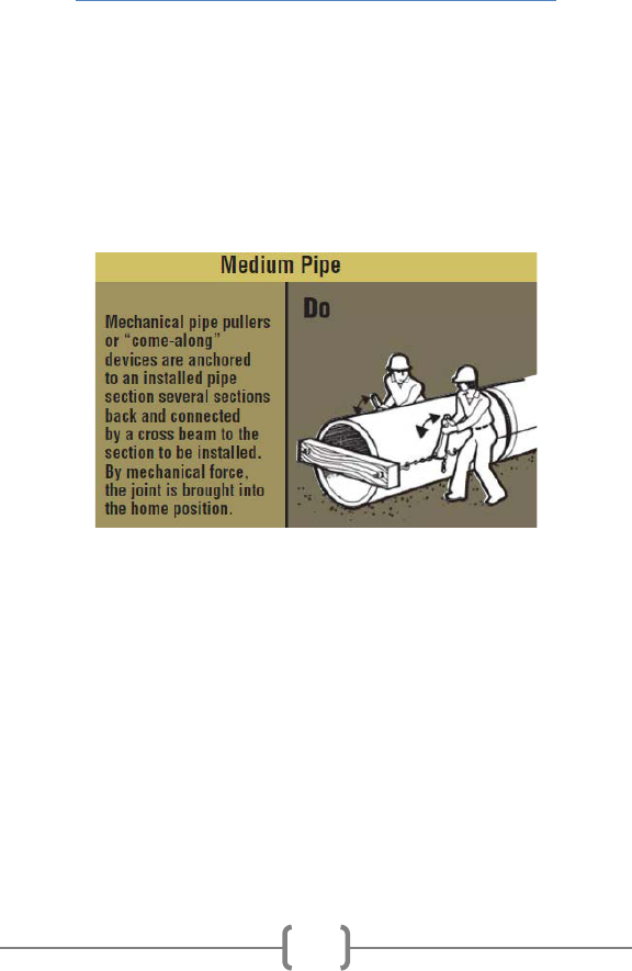
Concrete Pipe & Precast Installation
45
installed section, and connected by means of a chain, or
cable, to the grab hook on the pipe to be installed. By
pulling the lever back, the spigot of the pipe being jointed
is pulled into the bell of the previously installed pipe
section. To maintain close control over the alignment of
the pipe, a laying sling can be used to lift the pipe section
slightly off the bedding foundation.
When jointing larger diameter pipe, and when granular
bedding is used, mechanical pipe pullers may be required.
Several types of pipe pullers, or “come along” devices,
have been developed, but the basic force principles are
the same.
Large diameter pipe can be jointed by placing a “dead
man” block inside the installed pipe, several sections back
from the last installed section, which is connected by
means of a chain or cable to a strong back placed across
the end of the pipe section being installed. The pipe is
pulled home by lever action similar to the external
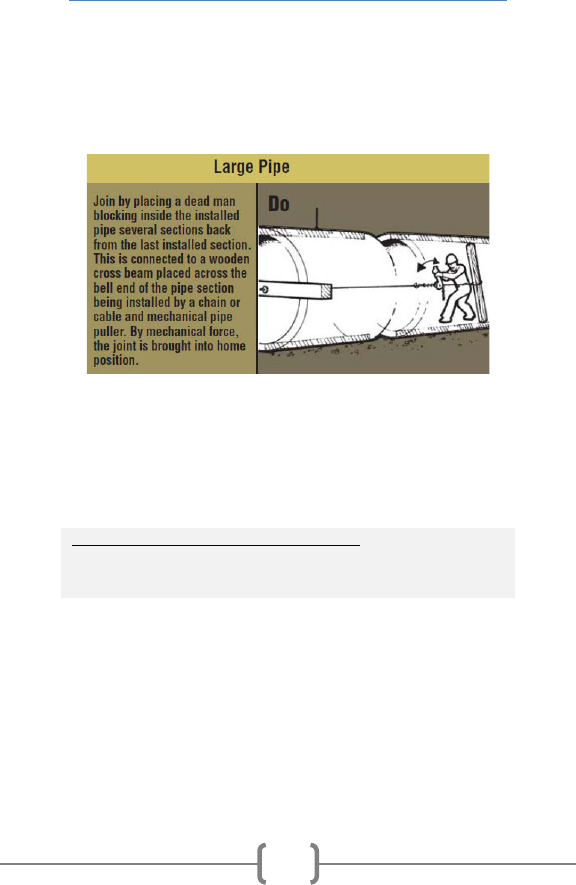
Concrete Pipe & Precast Installation
46
assembly. Mechanical details of the specific apparatus
used for pipe pullers, or come along devices, may vary, but
the basic lever action principle is used to develop the
necessary controlled pulling force.
Note: The excavating equipment must not be used to
push pipe sections together or to adjust pipe to the final
grade. The force applied by such equipment can damage
pipe joints.
References in Ontario Provincial Standards:
OPSS 410
Pipe Sewer Installation In Open Cut
OPSS 421
Pipe Culvert Installation In Open Cut

Concrete Pipe & Precast Installation
47
Jointing Procedures for Pre-lubricated Gasket
with Single Offset Joints
The unique design of the pre-lubricated pipe gasket
requires no field lubrication and no equalization after
installation.
Installation:
1. Ensure that concrete bell and spigot are free from
cracks, chips, or other defects.
2. Brush loose dirt, debris and foreign material from the
inside surface of the bell, the spigot and the gasket.

Concrete Pipe & Precast Installation
48
3. Stretch gasket around the spigot, with the “Nose”
against the step formed in the spigot, and the “Tube”
lying flat against the spigot.
4. Pre-lubricated gaskets do not typically require
equalization of the rubber gasket stretch. If
equalization is required, run a smooth round object
around the circumference several times.
5. Do not lubricate the gasket or joint as this could
adversely affect the performance of the gasket and
the joint.
6. Align the spigot with the bell, and thrust the spigot
home using suitable mechanical means. The homing
process will cause the lubricated tube to “roll” over

Concrete Pipe & Precast Installation
49
itself, above the compression section, allowing the
pipe to slide forward.
Once the pipe is fully homed,
The compression section seals the total annular space
The rolling tube comes to rest within the small
annular space – acting as a cushion against side loads
The serrations act to resist pipe pull-out.
Source: Hamilton Kent.

Concrete Pipe & Precast Installation
50
Jointing Procedures for O-Ring Gasket
Procedure Prevention
Clean all foreign material
from the jointing surface of
the bell end of the pipe.
Foreign material on the
jointing surface can prevent
proper homing of the pipe.
Carefully clean the spigot
end of the pipe, including
the gasket recess.
Spigot ends that are not
properly cleaned may
prevent proper sealing of
the gasket.

Concrete Pipe & Precast Installation
51
Procedure Prevention
Cover the entire jointing
surface using an approved
lubricant, using a brush,
cloth, sponge or gloves.
Bells and spigots which are
not properly lubricated can
cause gaskets to roll, or
possibly damage the joint.
Lubricate the spigot end of
pipe, especially the gasket
recess.

Concrete Pipe & Precast Installation
52
Procedure Prevention
Lubricate gasket before
inserting it on the spigot.
Excessive force will be
required to push the pipes
together if lubricant is
insufficient. This can cause
extensive damage.
When fitting the gasket,
equalize the gasket stretch
by running a smooth round
object around the
circumference several
times.
Unequal stretch can cause
bunching of the gasket and
can damage the bell or be
the source of leaks.

Concrete Pipe & Precast Installation
53
Procedure Prevention
When aligning the pipes,
before homing the joint,
check the gasket is in
contact with the entry
taper around the entire
circumference.
Improper alignment can
dislodge the gasket causing
leaks or possibly break the
bell.

Concrete Pipe & Precast Installation
54
How to Use Lift Anchors for Setting Pipe
The following procedures are published in Guidelines for
Handling Concrete Pipe and Utility Products by Dayton
Superior, and available from the OCPA.
Lift anchors in concrete pipe can be used to “home” or pull
the product into its final position with a three-legged chain
sling, as shown below.
1. The pipe is first transported to the installation site with the
symmetrical sling and lowered close to the already placed
pipe.

Concrete Pipe & Precast Installation
55
2. The long leg of the Pipe Laying Sling is attached to the
farthest anchor on the previously laid pipe. The free leg is
attached – out of the way – on the clevis link provided.
3. Locate the center of lift over the closest anchor of the
previously laid pipe. This will properly align the direction of
pull.
4. The pipe is pulled into position by slowly raising the boom
on the crane or backhoe without moving the boom forward
or backward.
5. When the pipe has been pulled into position, the load is
released and the Pipe Laying System is moved to the next
pipe, and the process is repeated.
Warning: Anchors can become overloaded and fail if the
crane or backhoe continues to apply load after the
connection has been completed.

Concrete Pipe & Precast Installation
56
Service Connections
Service connections to the main pipe sewer should be
made using factory made tees or wyes, strap-on-saddles,
or other approved saddles. OPSS 410 requires factory
made tees or wyes for all service connections where the
diameter of the main pipe sewer is:
Less than 450 mm, or
Less than twice the diameter of the service
connection.
Holes in the main pipe sewer should be cut with approved
cutters and should be the minimum diameter required to
accept the service connection. If mortar-on saddles are
used, the inside of the pipe should be mortared at the
connection.
Where existing service connections are to be connected to
new pipe sewers or service connections, proper jointing
procedures must be used.
References in Ontario Provincial Standards:
OPSS 410
Pipe Sewer Installation In Open Cut
OPSD
708.010
Catch Basin Connection for Rigid Main Pipe Sewer
OPSD
1006.010
Sewer Service Connections for Rigid Main Pipe
Sewer
Changes in Alignment
Maintenance holes should be used when there is a need to
change alignment, grade or size of a pipeline. Alignment

Concrete Pipe & Precast Installation
57
changes in concrete pipe sewers can also be incorporated
into the line through the use of deflected straight pipe,
radius pipe, or bends. Since manufacturing and
installation feasibility are dependent on the particular
method used to negotiate a curve, it is important to
establish the method prior to excavating the trench.
For deflected straight pipe, the joint of each pipe
section is opened on one side while the other side
remains in the home position. The difference
between home and opened joint space is generally
designated as the pull. The maximum permissible pull
must be limited to that opening which will provide
satisfactory joint performance. This varies for
different joint configurations and is best obtained
from the pipe manufacturer.
When establishing alignment for radius pipe, the first
section of radius pipe should begin one half of a
radius pipe length before the beginning of curve, and
the last section of radius pipe should extend one half
of a radius pipe length beyond the end of curve.
When extremely sharp curves are required, deflected
straight pipe or radius pipe may not be suitable. In
such cases, bends or elbows may be used.
Since manufacturing processes and local standards vary,
local concrete pipe manufacturers should be consulted to
determine the geometric configurations available.

Concrete Pipe & Precast Installation
58
MH INSTALLATION
Structures must be installed on firm foundations at the
locations and elevations specified, and must be
constructed plumb and true to alignment.
Precast base slabs or monobases must be placed level
before subsequent sections complete with joint seal
systems be installed. Adjustment of the structure should
be carried out by lifting the affected sections free of the
excavation, re-leveling the base, if necessary, and re-
installing the sections. Damaged sections and gaskets
must be replaced.
When specified, the inside concrete bottom of the
structures should be benched and channeled to
accommodate the pipe. Concrete benching should have a
wood float finish and the channel should have steel trowel
finish. The channel must be smooth and flush with
adjacent pipe inverts.
Obtaining maintenance hole invert levels for the
preparation of as-built drawings, combined with visual
inspection of the sewer, provide an additional check that
settlement has not occurred.
References in Ontario Provincial Standards:
OPSS 407
Maintenance Hole, Catch Basin, Ditch Inlet, and
Valve Chamber Installation
OPSD
701.021
Maintenance Hole Benching and Pipe Opening
Alternatives

Concrete Pipe & Precast Installation
59
Prebenched MH Monobases
Having the precast MH base prebenched at the factory
offers advantages over benching in the field. Prebenching
is done under controlled conditions, resulting in a higher
quality product.
When used with flexible connectors, there is no need for
workers to enter the confined space created when the
maintenance hole is backfilled.
MH Connections
When the pipe connects to a rigid structure such as a
maintenance hole, it may shear or crack at the connection,
as a result of differential settlement. It is essential that
the bedding and foundation for the connecting pipe
section be highly compacted, to minimize differential
settlement.
Two methods are recommended by the precast concrete
pipe industry to maintain a watertight structure:
Flexible pipe-to-MH connectors. The flexible
connectors consist of a pre-formed rubber boot
inserted in the MH wall opening. The pipe is inserted
in the boot and the rubber connector is tightened to
create a positive connection.
Concrete grout. For many large diameter sewer
applications, contractors may connect directly to
MH’s using grout.

Concrete Pipe & Precast Installation
60
OPSS 407 requires that one of the following connections
be provided where a pipe connects to a structure:
A flexible pipe joint be provided within 300 mm of the
outside face of the structure for flexible and rigid
pipe.
A concrete cradle to the first joint for rigid pipe.
A resilient connector, i.e., a flexible, watertight
connector, in the structure opening for flexible and
rigid pipe.
A special approved structure designed for pipe
support.
Installation of pipe connectors must be according to the
manufacturer’s recommendations.
All pipes, except in valve chambers, must be flush with the
inside walls of the structure.
References in Ontario Provincial Standards:
OPSS 407
Maintenance Hole, Catch Basin, Ditch Inlet, and
Valve Chamber Installation
OPSS 410
Pipe Sewer Installation In Open Cut
OPSD
708.020
Support For Pipe at Catch Basin or Maintenance
Hole

Concrete Pipe & Precast Installation
61
Precast Concrete Adjustment Units
Precast concrete adjustment units can be used to set the
frame with grate or cover at the required position and
elevation. OPSS 408 requires a minimum of one
adjustment unit, but not more than three adjustment units
at each structure to a maximum height of 300mm.
The first adjustment unit should be laid in a full bed of
mortar and aligned with the opening in the structure.
Successive adjustment units are laid plumb to the first
adjustment unit and should be sealed between each unit.
Frames with Grates or Covers
When precast concrete adjustment units are used, frames
with grates or covers should be set in a full bed of mortar
on the adjustment units.
Ditch inlet grates should be installed as specified by the
precast manufacturer, or grate supplier.
Catchbasin grates which lie within the flow lines of a curb
and gutter system should be according to OPSS 353.
References in Ontario Provincial Standards:
OPSS 407
Maintenance Hole, Catch Basin, Ditch Inlet, and
Valve Chamber Installation
OPSS 408
Adjusting or Rebuilding MH, CB, Ditch Inlet and
Valve Chambers
OPSD
704.010
Precast Concrete Adjustment Units for
Maintenance Holes, Catch Basins, and Valve
Chambers

Concrete Pipe & Precast Installation
62
BOX UNIT INSTALLATION
Box units must be installed to the alignment and grade
specified in the contract documents. Installation of the
box units should start at the outlet end and proceed in the
upstream direction with the bell ends of the box units
facing upgrade.
OPSS 422 requires that the gap at box unit joints must not
exceed 20mm. Digging a small trench in the bedding at
each box joint with a round point shovel across the full
width of the box unit will ensure a proper alignment and
connection. This allows for the excess bedding material to
fall into the trench instead of getting trapped in the joint
as the next box unit is pulled into place.
For box units placed in parallel for multiple cell
installations, a 60mm ± 10mm gap filled with grout to
provide positive lateral bearing between adjacent cells.
For more information on precast concrete box, refer to the
OCPA Precast Box & Culvert Guideline.
Foundations
Precast box units should be constructed as specified in the
contract. The foundation must be firm in-situ soil, or
compacted backfill to provide uniform support for the full
length and width of each box unit. The foundation on
each side of the box unit, for a minimum distance equal to
the inside width of the box unit should be at least as stable
as the foundation directly below the box unit. Bedding
should not be placed on frozen earth.

Concrete Pipe & Precast Installation
63
Bedding
The maximum particle size for bedding should not exceed
25 mm in diameter, unless the bedding layer is at least 150
mm thick, in which case the maximum particle size should
not exceed 38 mm in diameter.
Bedding requiring compaction should be placed in layers
not exceeding 200 mm in thickness, loose measurement,
and each layer should be compacted before a subsequent
layer is placed.
The type of equipment used must be
suited to the material to be compacted, degree of
compaction required, and space available.
Levelling
The surface prepared to support the box units should have
a 75 mm minimum thickness top leveling course of
uncompacted Granular A or fine aggregates.
Backfill and Cover
Backfill and Cover should be placed in layers not exceeding
200mm in thickness, loose measurement, and each layer
should be compacted according to OPSS 501.
Backfilling on each side of the box units should be
completed simultaneously. The levels on each side must
not differ by more than 400mm.

Concrete Pipe & Precast Installation
64
Distribution Slab
Precast concrete box installed with a height of fill less than
0.60m typically requires a reinforced distribution slab
across the entire top of the box units, as detailed in OPSD
3920.110.
References in Ontario Provincial Standards:
OPSS 422
Precast Reinforced Concrete Box Culverts and Box
Sewers In Open Cut
OPSD
3920.100
Precast Reinforced Concrete Box Culvert with
Height of Fill ≥ 0.6m
OPSD
3920.110
Precast Reinforced Concrete Box Culvert with
Height of Fill < 0.6m
FIELD TESTING
The physical tests included in the material specifications,
under which the pipe is purchased, assure that pipe
delivered to the jobsite meets, or exceeds the
requirements established for a particular project. The
project specifications usually include acceptance test
requirements to assure that reasonable quality control of
workmanship and materials have been realized during the
construction phase of the project. Tests applicable to all
storm sewer, sanitary sewer and culvert projects are soil
density, line and grade and visual inspection, often by
video. For sanitary sewers, leakage limits are usually
established for infiltration or exfiltration.

Concrete Pipe & Precast Installation
65
Soil Density
To correlate in-place soil densities with the maximum
density of a particular soil, it is first necessary to determine
the Optimum Moisture Content for maximum compaction,
and then use this as a guide to determine the actual
compaction of the fill, or backfill. Several test procedures
have been developed for measuring in-place soil densities.
The maximum dry density can be determined by LS-706 or
LS-623 for granular and by LS-706, for earth. These tests
can be found in the MTO Laboratory Testing Manual:
• LS-623 - One Point Proctor Test (OPT)
• LS-706 - Moisture - Density Relationship of Soils Using
2.5 kg Rammer and 305 mm Drop
Field density and field moisture determinations can be
made in accordance with:
• ASTM D 2922 - Standard Test Methods for Density of
Soil and Soil-Aggregate in Place by Nuclear Methods
(Shallow Depth); and
• ASTM D 3017- Standard Test Method for Water
Content of Soil and Rock in Place by Nuclear Methods
(Shallow Depth)
A nuclear moisture and density gauge provides a rapid,
non-destructive technique for in-place determination of
density suitable for control and acceptance testing of soils.
It should be noted that the equipment utilizes radioactive

Concrete Pipe & Precast Installation
66
materials, which may be hazardous to the health of users,
unless proper precautions are taken.
References in Ontario Provincial Standards:
OPSS 501
Compacting
Visual/Video Inspection
Larger pipe sizes can be entered and examined, while
smaller sizes must be inspected by means of closed circuit
television cameras.
The following is a checklist for CCTV inspection of a pipe:
• debris and obstructions
• cracks exceeding the 0.3 mm wide design crack
for reinforced concrete pipe
• joints properly sealed
• invert smooth and free of sags or high points
• stubs properly grouted and plugged
• laterals, diversions, and connections properly
made
• catchbasins and inlets properly connected
• maintenance hole frames and grates properly
installed
• surface restoration, and all other items pertinent
to the construction, properly completed
References in Ontario Provincial Standards:
OPSS 409
Closed-Circuit Television Inspection Of Pipelines

Concrete Pipe & Precast Installation
67
Infiltration Testing
The infiltration of excessive ground water into a sanitary
sewer can overload the capacity of a sewer collection
system and treatment facilities. The infiltration test is
intended to demonstrate the integrity of the installed
materials and construction procedures as related to the
infiltration of ground water. Infiltration tests should be
conducted where the groundwater level at the time of
testing is 600 mm or more above the crown of the pipe for
the entire length of the test section. The test section is
normally between adjacent maintenance holes.
• Discontinue dewatering operations at least three days
before conducting the test and allow the
groundwater level to stabilize.
• A watertight bulkhead is constructed at the upstream
end of the test section.
• All service laterals, stubs, and fittings are plugged or
capped to prevent water entering at these locations.
• A V-notch weir or other suitable measuring device is
installed at the downstream end of the test section.
• Infiltrating water is allowed to build up behind the
weir until the flow through the V-notch has stabilized.
• The rate of flow is then measured.
In OPSS 410, the allowable infiltration is calculated as
0.075 litres/mm diameter/100 m of pipe sewer/hour.
References in Ontario Provincial Standards:
OPSS 410
Pipe Sewer Installation In Open Cut

Concrete Pipe & Precast Installation
68
Exfiltration Testing
Exfiltration tests should be conducted where the
groundwater level is lower than 600 mm above the crown
of the pipe or the highest point of the highest service
connection included in the test section.
The test section is normally between adjacent
maintenance holes. The test section of the pipe sewer
shall be isolated by temporarily plugging the downstream
end and all incoming pipes of the upstream maintenance
hole. All service laterals, stubs, and fittings are plugged or
capped to prevent water entering at these locations.
Since sanitary sewers are not designed, or expected to
operate as a pressure system, care must be exercised in
conducting the test and correlating the results with
allowable exfiltration limits.
References in Ontario Provincial Standards:
OPSS 410
Pipe Sewer Installation In Open Cut
Testing With Water
The test section is slowly filled with water making sure
that all air is removed from the line.
The test procedure outlined in OPSS 410 is as follows:
• A period of 24 hours for absorption or expansion may
be allowed before starting the test, except if

Concrete Pipe & Precast Installation
69
exfiltration requirements are met by a test carried
out during the absorption period.
• Water can be added to the pipeline prior to testing
until there is a head in the upstream maintenance
hole of 600 mm minimum over the crown of the pipe
or at least 600 mm above the existing groundwater
level, whichever is greater.
• The maximum limit of the net internal head on the
line is 8 m.
• In calculating net internal head, allowance for
groundwater head, if any, should be made.
• The distance from the maintenance hole frame to the
surface of the water should be measured.
• After allowing the water to stand for one hour, the
distance from the frame to the surface of the water
shall again be measured.
• The leakage should be calculated using volumes. The
leakage at the end of the test period must not exceed
the maximum allowable calculated for the test
section.
• In OPSS 410, the allowable leakage is calculated as
0.075 litres/millimetre diameter/100 metres of pipe
sewer/hour. An allowance of 3.0 litres per hour per
metre of head above the invert for each maintenance
hole included in the test section shall be made.
• Maintenance holes must be tested separately, if the
test section fails.

Concrete Pipe & Precast Installation
70
Low Pressure Air Testing
IMPORTANT
OPSS 410 outlines a Low Pressure Air Test that is also
found in CSA B182.11 for thermoplastic pipe, and the
Uni-Bell Handbook for PVC Pipe. The current OPSS 410
air test was originally intended for PVC pipe and is not
appropriate for concrete pipe installations. An air
leakage test designed specifically for concrete pipe
(ASTM C924) was withdrawn in 2013 due to safety
concerns. Contact the OCPA for more information.
Leakage Test Acceptance
• Leakage up to 25% in excess of the calculated limits
may be approved in any test section provided that
the excess is offset by lower leakage measurements
in adjacent sections such that the total leakage is
within the allowable limits for the combined sections.
• Pipe sewers must be repaired and retested, as
required, until the test results are within the limits
specified in OPSS 410.
• Visible leaks must be repaired regardless of the test
results.
• No part of the work will be accepted until the pipe
sewers are satisfactorily tested following completion
of installation of service connections and backfilling.
References in Ontario Provincial Standards:
OPSS 410
Pipe Sewer Installation In Open Cut

Concrete Pipe & Precast Installation
71
APPENDIX

Concrete Pipe & Precast Installation
72
APPENDIX A – Concrete Jacking Pipe
For jacked or tunneled installations, concrete pipe must be
capable of withstanding the longitudinal, or axial, jacking
forces encountered during installation. CSA A257.2
prescribes the following minimum requirements for
concrete jacking pipe:
• minimum concrete strength of 40 MPa
• only circular reinforcing cages can be used
• inner cage reinforcement must extend into the spigot
• the length of opposite sides of any section of pipe
must be within 6 mm of each other
• all other requirements for reinforced concrete pipe
specified in CSA A257 must be met
In all jacking operations, the direction and jacking distance
should be carefully established prior to beginning the
operation. The first step of any jacking operation is the
excavation of jacking pits, or construction shafts, at each
end of the proposed line. The shaft from which pipe is to
be jacked should be of sufficient size to provide ample
working space for spoil removal, and room for the jacking
head, jacks, jacking frame, reaction blocks and one or two
sections of pipe.
An accurate control point must be established at the
bottom of the construction shaft. Provision should be
made for the use of guide rails in the bottom of the shaft.
For large pipe, it is desirable to set rails in a concrete slab.
Close control of horizontal and vertical alignment can be
obtained by laser or transit.

Concrete Pipe & Precast Installation
73
The number and capacity of jacks depend on the size and
length of the pipe to be jacked, and the type of soil. The
size of excavation should coincide as closely as possible to
the outside diameter of the pipe. The wall of the
excavation is typically 25 to 50 mm larger than the pipe,
and hydraulically operated jacks should have the capacity
to ensure smooth and uniform advancement without over-
stressing the pipe.
The excavated material is loaded into carts, or deposited
onto a conveyor system, and then transported through the
pipe to the jacking pit. Since the rate of progress of a
jacking or tunneling operation is usually controlled by the
rate of excavation and spoil removal, preliminary
investigation and advance planning for fast and efficient
removal and placement of spoil, is important in preventing
delays.
Correct alignment of the pipe guide frame, jacks and
backstop is necessary for uniform distribution of the axial
jacking force around the periphery of the pipe. By assuring
that the pipe ends are parallel and the jacking force
properly distributed through the jacking frame to the pipe
and parallel with the axis of the pipe, localized stress
concentrations are avoided. A jacking head is often used
to transfer the pressure from the jacks, or jacking frame to
the pipe.
The usual procedure in jacking concrete pipe is to equip
the leading edge with a jacking head, or shield, to protect

Concrete Pipe & Precast Installation
74
the lead pipe by distributing the jacking pressure uniformly
over the entire end bearing area of the pipe. In addition to
protecting the end of the pipe, a jacking head helps keep
the pipe in proper line by maintaining equal pressure
around the circumference of the pipe.
As succeeding lengths of pipe are added between the lead
pipe and the jacks, and the pipe is jacked forward, soil is
excavated and removed through the pipe. This procedure
usually results in minimum disturbance of the earth
adjacent to the pipe. Use of a lubricant, such as Bentonite,
to coat the outside of the pipe is helpful in reducing
surface friction, and soil adhesion if the jacking operation
is interrupted. Because of the tendency of soil friction to
increase with time, it is usually desirable to continue
jacking operations, without interruption, until completed.
The use of a cushion material such as plywood or MDF
between adjacent pipe sections provide uniform load
distribution throughout the entire pipe length being
jacked. The contact surfaces of all pipe joints that transmit
the axial jacking forces must be separated by a packer of
plywood with a minimum thickness of 13mm (1/2 in.) for
pipe 900 mm in diameter or smaller and 19mm (3/4 in.)
for pipe larger than 900 mm, or another material of
equivalent or lesser stiffness that can transmit the axial
jacking forces uniformly and without producing significant
transverse splitting forces.
Pipe installed by jacking or tunneling may require the void
between the pipe and the excavation to be filled. Sand,

Concrete Pipe & Precast Installation
75
grout, concrete, or other suitable material should be
injected into the annular space. This can be accomplished
by installing special fittings into the wall of the pipe.
References in Ontario Provincial Standards:
OPSS 416
Pipeline and Utility Installation By Jacking and
Boring
Other useful references:
American Society of Civil Engineers (ASCE)
ASCE 27 – Standard Practice for Direct Design of
Precast Concrete Pipe for Jacking in Trenchless
Construction
ASCE 36 – Standard Design and Construction
Guidelines for Microtunneling

Concrete Pipe & Precast Installation
76
APPENDIX B – Damage Assessment
The Ontario Concrete Pipe Association supports third party
certification by the Canadian Precast Concrete Quality
Assurance (CPCQA) certification program which was
developed to ensure precast concrete drainage products
leave the manufacturing facility in conformance to the
program. Furthermore, the CPCQA engineer as well as the
OCPA can provide invaluable experience in the assessment
of damaged pipe.
In addition to the information provided in this section, a
useful reference is ASTM C1840 Standard Practice for
Inspection and Acceptance of Installed Reinforced Concrete
Culvert, Storm Drain, and Storm Sewer Pipe.
Repair Types
It is important to properly assess the damage on precast
concrete products and determine if it requires either a
structural repair, or a non-structural, cosmetic repair. The
following definitions could be used as a guide to
distinguish the two:
• Structural Repair - A defect that meets one or more
of the following criteria:
• Main reinforcement steel is exposed
• Damage occurs in load bearing areas
• Embedded connection hardware is exposed
• Cracking extends from one face through the wall
to the opposite face
• Cracks in structural elements are larger than
2.5mm in width

Concrete Pipe & Precast Installation
77
• Cosmetic Repair – A defect in the appearance of the
product which does not affect its performance, and
does not meet the criteria for a Structural Repair.
In CSA A257 - Standards for Concrete Pipe & Manhole
Sections, precast concrete may be repaired, when
necessary, because of imperfections in manufacture or
damage during handling and is acceptable if:
• The repairs are sound and properly finished and
cured.
• The repaired concrete conforms to all other
requirements of CSA A257.
Any repair must provide the strength and durability of
the original concrete.
Joint Integrity
Pipe joints are routinely checked at the plant for
dimensional accuracy and to ensure that all surfaces of the
joint that comes in contact with the gasket is smooth and
free of imperfections that could adversely affect the
performance of the joint. The rubber gaskets are designed
and tested to permit easy assembly while providing a
watertight flexible seal. In spite of this attention to joint
leakage prevention, leaks still can occur in the field due to
handling damage or adverse installation conditions.
In CSA A257.3 - Joints for Circular Concrete Sewer and
Culvert Pipe, Manhole Sections, and Fittings using Rubber
Gaskets, clause 7.1 states:

Concrete Pipe & Precast Installation
78
Spalled areas, manufacturing imperfections, or damage (to
joints) caused during handling of each pipe may be
repaired and shall be considered acceptable if the repaired
pipe or maintenance hole section conforms to the
requirement of Clause 5.1.3 and provided that:
• The circumferential length of a single area to be
repaired does not exceed 1/4 the inside diameter of
the pipe; or
• The combined circumferential lengths of several
areas do not exceed 1/2 the inside diameter of the
pipe.
The following are a few problems typically experienced
during installation and preventative measures that should
be taken.
Prevention of common problems with pipe joints:
Problem Prevention
Rebounding Joint
Opening
• Proper joint lubricant, if
applicable
• Protect gasket from extreme
heat and cold
•
Use self-lubricating gaskets
Rolling or Sliding
Gasket
• Clean the joint surface and
lubricate both the bell and
gasket surface
• No lubricant required for
roll-on gaskets
• Proper location of gasket on
the spigot
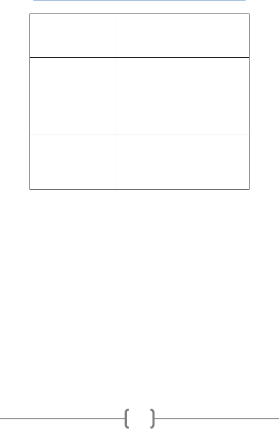
Concrete Pipe & Precast Installation
79
Damaged
• Maintain proper storage and
handling procedures in
accordance with previous
sections in this guide.
Deflected Joints
• Check line and grade
settings. Good alignment
results in good joint
performance
• Follow proper installation
procedures
• Prepare a stable foundation
Hanging Gaskets
• Stable foundation
• Proper construction of
bedding under barrel of pipe
• Proper compaction under
maintenance holes
Cracks
Reinforced concrete pipe is designed to permit cracking.
The design crack, 0.3mm in width over a length of not less
than 300mm is the measure used. Not understanding this
process, cracking of reinforced concrete pipe can present a
concern to infrastructure owners.
Cracks in reinforced concrete pipe are generally
discovered through video surveys or visual assessments
done as a requirement of the contract. Timing of such
inspection is typically prior to the assumption of an
installed system by the owner. It is very important that
owners undertake these types of inspections to elevate
the accountability of all those involved in the satisfaction

Concrete Pipe & Precast Installation
80
of the contract. There can be no denying that proper
installation and inspection will have a tremendous impact
on the satisfaction of the expected service life of new
system. In order for owners to achieve a final project with
the goals of economic and adequate serviceability, proper
assessment must be stressed. Issues, which may arise in
the evaluation of cracks include:
• Width
• Length
• Orientation
• Location
• Severity
This section will address each of these issues.
Width
The design (service) crack used in reinforced concrete pipe
is the 0.3mm crack over a length of at least 300mm. This
crack will generally appear at the invert (and occasionally
the obvert) of the concrete pipe since the highest tensile
stress occurs at these locations. The design crack is V-
shaped in nature and is widest at the surface penetrating
usually no further than the first reinforcing cage in the
pipe. It is very difficult to determine the magnitude or
significance of a crack and the unavoidable magnification
of the crack in the pipe that is inherent with video
inspection technology today. As a result it is critical that
analysis of sewer video be done by trained personnel.

Concrete Pipe & Precast Installation
81
Hairline cracks are extremely fine cracks, narrower than
design cracks yet can be visible during video inspections.
Hairline cracks are often mistaken as design cracks, yet the
hairline crack is in fact the prelude to the appearance of
the design crack, which will generally not occur.
Shrinkage cracks can occur during the curing process of
reinforced concrete pipe. As concrete cures, moisture
disappears from the concrete matrix. Depending on the
rate of curing, shrinkage cracks can occur, i.e. the more
rapid the curing, the greater likelihood of shrinkage cracks.
Shrinkage cracks are generally hairline type cracks
appearing circumferentially on the outer surface of the
pipe barrel and quite often do not penetrate into the pipe
wall.
The width of a crack is a critical consideration when
determining the impact on the durability and or structural
integrity of an installed reinforced concrete pipe.
Length
The length of a crack is rarely an indication of poor quality
material or improper installation practices. In most if not
all conditions where a crack is evident in a pipe, the width
and location of the crack is more critical to understand and
evaluate.
Orientation
Longitudinal cracks run lengthwise along the barrel of the
pipe and can be single cracks or in some instances of

Concrete Pipe & Precast Installation
82
severe damage can become multi-directional in
appearance. Circumferential cracks run around the barrel
of the pipe and may or may not propagate the full inner
circumference of the pipe barrel.
Location
Understanding how pipe performs in the installed
condition is critical when evaluating the location of a
crack.
Longitudinal cracks visible at the invert or obvert of the
pipe are indications the pipe has accepted the load to
which it was designed.
Longitudinal cracking at any other location along the inside
barrel of the pipe can generally be attributed to poor
construction practices which may include but are not
limited to improper handling or weak installation and
backfilling techniques. Pipe installations in certain rock
formations, particularly some types of shales, exhibit a
tendency to expand and may result in “rock squeeze”. In
parts of Southern Ontario, an overwhelming amount of
evidence has been accumulated over the years on the
detrimental effect of rock squeeze on underground
structures.
Multi-directional longitudinal cracking, an indication the
pipe has been subjected to some sort of impact load, can
most certainly be attributed to the lack of care taken when
installing or handling the pipe. This evidence should be

Concrete Pipe & Precast Installation
83
considered carefully when assessing the integrity and
future performance of the installed pipe.
Circumferential cracks are in no way attributed to the
installation conditions to which the pipe was designed to
handle. In fact, cracks propagating circumferentially on
the inner surface of the pipe can be attributed in most
cases to differential settlements in the pipe bedding. This
condition can result from uneven placement and over-
compaction of the bedding material creating point loads
along the barrel of the pipe. Furthermore, failure to dig
‘bell holes’ to accept a protruding pipe bell, a feature of
many small to mid-range diameter pipe, can lead to the
development of circumferential cracking at or just beyond
the pipe joint.
Severity
The key to determining if structural concerns exist is the
degree or severity of the damage to the pipe. Hairline and
design cracks are not a result of damage to the pipe and
therefore needn’t be considered for repair. Otherwise,
longitudinal and circumferential cracking is an indication of
damage to which the severity must be assessed. As
discussed later, autogenous healing is a powerful process
in the repair of minor damage sustained by a concrete
pipe. In most if not all cases where autogenous healing
has sealed the defect, the integrity of the pipe should be
considered sound. Pipe cracking or damage beyond the
scope of autogenous healing must be evaluated further.

Concrete Pipe & Precast Installation
84
Cracks where concrete has been displaced must be
considered for a structural type of repair. Also of concern
would be a crack or defect that is allowing water to
infiltrate into the pipe system. The infiltration can be
relatively clear or it can be a ‘rust-like’ colour. The latter is
an indication the steel in the pipe is being impacted by
water. Regardless, both situations require remediation,
the extent of which must be assessed on the amount of
the infiltration and structural damage.
Basis of Acceptance
The final acceptance of the rehabilitation of reinforced
concrete pipe should be subject to visual or video
inspection. This is the only way to ensure the ultimate
owner of the system has assurance that the pipeline will
be durable and achieve its intended service life. During
the evaluation process of video inspection, the owner
must be aware of what the video is actually showing.
Distortion can occur due to the presence of water or to
magnification of the video. To properly evaluate the
extent of a crack, actual measurements must take place. If
this is not possible due to the size of the pipe, the owner
should rely on professional judgment. The practitioner
should look for the visible signs of structural damage. If
the crack appears wide, and the pipe is displaced on either
side of the crack, or the location of the crack is not
conducive with the design crack, concern is justified. If no
displacement is apparent, the process of Autogenous
Healing will, in all likelihood, seal the crack and ensure the
longevity of the reinforced concrete pipe can be achieved.

Concrete Pipe & Precast Installation
85
Autogenous Healing
This phenomenon occurs between opposing surfaces of
narrow cracks. The mechanism of the healing is the hard
white ‘crust like’ formation on the concrete pipe known as
calcium carbonate. The crack healing requires the
presence of moisture, which when reacting with cement
powder, restarts the hydration (curing) process.
The strength of the healed crack has been studied under
laboratory conditions. It has been suggested that full
healing creates a monolithic structure, so the pipe is “as
good as new”, and should be considered structurally
sound and capable of performing in the manner originally
intended.
Regardless of the mechanism, autogenous healing will
occur in concrete pipe that has cracked. Some literature
has reported cracks as wide as 1.5mm healed in a period
of 5 years and cracks of 0.2mm healed completely within 7
weeks. It appears that the narrower the crack, the more
rapid the healing can occur. The Ohio DOT Supplemental
Specification 802 - Post Construction Inspection of Storm
Sewers and Drainage Structures identifies the
rehabilitation methods for installed pipe which has
evidence of cracking. The specification requires the
contractor to “Do Nothing” for cracks up to 1.8mm in
width, with the expectation that autogenous healing will
create a watertight pipe over a period of a few years.

Concrete Pipe & Precast Installation
86
Rehabilitation Techniques
The National Association of Sewer Service Companies
(NASSCO) maintains invaluable information on the
installation and rehabilitation of pipelines and
maintenance holes as provided by its members. The
NASSCO Specification Guidelines are intended to assist
engineers and municipal officials to properly specify sewer
rehabilitation work and include the following topics:
• CCTV/Inspection
• Cleaning
• Coatings
• Centrifugally Cast Concrete Pipe (CCCP)
• Cured-In-Place-Pipe (CIPP Mainline Pipes)
• Fold and Form/Folded and Reformed
• Grouting/Joint Sealing
• Lateral/Renewal Repair
• Manhole
• Pipe bursting
• Point Repair/Spot Repair
• Pumping
• Roll Down/Diameter Reduction
• Root Control
• Testing
Open communication between the owner and the
concrete pipe industry may draw on many years of
experience and lead to accurate assessments of installed
infrastructure and the implementation of the appropriate

Concrete Pipe & Precast Installation
87
remedial action necessary to ensure damaged pipe
satisfies project design life criteria.
Chemical Grout
The American Society for Testing and Materials (ASTM)
specifications can provide information on the
rehabilitation of sewers and maintenance holes using
chemical grouting. Chemical grouting is used to stop
infiltration of ground water and exfiltration of sewage in
gravity flow sewer systems that are structurally sound.
Knowledge of chemical additives can increase the
performance of a chemical grout for varying conditions.
Additives can:
• Increase strength
• Reduce shrinkage
• Increase viscosity
• Assist in the filling of large voids
• Inhibit root growth
• Resist low temperatures
ASTM F2304 - Standard Practice for Sealing of Sewers
Using Chemical Grouting describes the procedures for
testing and sealing individual sewer pipe joints with
appropriate chemical grouts. This practice applies to
sewers 150 to 1050 mm in diameter. Larger diameter pipe
may be grouted with specialized packers or man entry
methods. This practice should not be used for
longitudinally cracked pipe, severely corroded pipe,
structurally unsound pipe, flattened, or out-of-round pipe.

Concrete Pipe & Precast Installation
88
ASTM F2414 - Standard Practice for Sealing Sewer
Manholes Using Chemical Grouting covers proposed
selection of materials, installation techniques, and
inspection required for sealing maintenance holes using
chemical grout.
ASTM F2454 - Standard Practice for Sealing Lateral
Connections and lines from the mainline Sewer Systems by
the Lateral Packer Method, Using Chemical Grouting
covers the procedures for testing and sealing sewer lateral
connections and lateral lines from the mainline sewer with
appropriate chemical grouts using the lateral packer
method. This practice applies to mainline sewer diameters
of 150 to 600 mm with 100, 125 or 150 mm diameter
laterals. Larger diameter pipes with lateral connections
and lines can be grouted with special packers or man-entry
methods. The mainline and lateral pipes must be
structurally adequate to create an effective seal.
Trenchless Technologies
Trenchless technology includes a wide range of methods
utilized for both new construction and rehabilitating
existing underground utility systems with minimal surface
disruption and destruction resulting from excavation.
The Centre for Advancement of Trenchless Technologies
(CATT) was established in 1994 to help municipalities
address their buried infrastructure challenges with specific
reference to trenchless technologies. CATT is a grouping
of university, municipal, industrial, business and

Concrete Pipe & Precast Installation
89
government agencies committed to the advancement of
knowledge, materials, methods and equipment used in
trenchless technologies.
For more information, visit www.catt.ca
.
References in Ontario Provincial Standards:
OPSS 409
Closed-Circuit Television Inspection of Pipelines
OPSS 415
Pipeline and Utility Installation by Tunneling
OPSS 416
Pipeline and Utility Installation by Jacking and
Boring
OPSS 450
Pipeline and Utility Installation in Soil by Horizontal
Directional Drilling
OPSS 460
Pipeline Rehabilitation by Cured-In-Place Pipe
OPSS 463
Pipeline and Conduit Installation by Pipe Bursting

Concrete Pipe & Precast Installation
90
References
1. Ontario Concrete Pipe Association (OCPA)
www.ocpa.com
• Concrete Pipe Design Manual
• Concrete Pipe Installation Guide
• Precast Box & Culvert Guideline
2. Ontario Provincial Standards for Roads and Public
Works (OPS)
www.ops.on.ca
• Specifications (OPSS)
• Drawings (OPSD)
3. Canadian Standards Association
www.csa.ca
• A257 Series – Standards for Concrete Pipe
and Manhole Sections
• A23.1 – Concrete Materials and Methods of
Concrete Construction
• CAN/CSA S6 – Canadian Highway Bridge
Design Code
4. Ontario Ministry of Labour
• Occupational Health and Safety Act
• Ontario Regulation (O. Reg.) 213/91 for
Construction Projects
5. Infrastructure Health & Safety Association
www.ihsa.ca
• Construction Health and Safety Manual

Concrete Pipe & Precast Installation
91
6. Dayton Superior Corporation
www.daytonsuperior.com
• Guidelines for Handling Precast Concrete
Pipe and Utility Products
7. American Concrete Pipe Association (ACPA)
www.concrete-pipe.org
• Concrete Pipe Design Manual
• Concrete Pipe Installation Guide
8. American Society for Testing and Materials (ASTM)
www.astm.org
9. National Association of Sewer Service Companies
(NASSCO)
www.nassco.org
• Specification Guidelines
10. Centre for Advancement of Trenchless Technologies
(CATT)
www.catt.ca

