
Agilent Technologies
OpenLAB CDS Report
Template Editor
Concepts Guide
Concepts Guide

Concepts Guide
Notices
© Agilent Technologies, Inc. 2009-2017
No part of this manual may be reproduced
in any form or by any means (including
electronic storage and retrieval or transla-
tion into a foreign language) without prior
agreement and written consent from Agi-
lent Technologies, Inc. as governed by
United States and international copyright
laws.
Manual Part Number
M8305-90023
Edition
09/2017
Printed in Germany
Agilent Technologies
Hewlett-Packard-Strasse 8
76337 Waldbronn
Warranty
The material contained in this docu-
ment is provided “as is,” and is sub-
ject to being changed, without notice,
in future editions. Further, to the max-
imum extent permitted by applicable
law, Agilent disclaims all warranties,
either express or implied, with regard
to this manual and any information
contained herein, including but not
limited to the implied warranties of
merchantability and fitness for a par-
ticular purpose. Agilent shall not be
liable for errors or for incidental or
consequential damages in connection
with the furnishing, use, or perfor-
mance of this document or of any
information contained herein. Should
Agilent and the user have a separate
written agreement with warranty
terms covering the material in this
document that conflict with these
terms, the warranty terms in the sep-
arate agreement shall control.
Technology Licenses
The hardware and/or software described in
this document are furnished under a
license and may be used or copied only in
accordance with the terms of such license.
Restricted Rights Legend
If software is for use in the performance of
a U.S. Government prime contract or sub-
contract, Software is delivered and licensed
as “Commercial computer software” as
defined in DFAR 252.227-7014 (June 1995),
or as a “commercial item” as defined in
FAR 2.101(a) or as “Restricted computer
software” as defined in FAR 52.227-19
(June 1987) or any equivalent agency regu-
lation or contract clause. Use, duplication
or disclosure of Software is subject to Agi-
lent Technologies’ standard commercial
license terms, and non-DOD Departments
and Agencies of the U.S. Government will
receive no greater than Restricted Rights as
defined in FAR 52.227-19(c)(1-2) (June
1987). U.S. Government users will receive
no greater than Limited Rights as defined in
FAR 52.227-14 (June 1987) or DFAR
252.227-7015 (b)(2) (November 1995), as
applicable in any technical data.
Safety Notices
CAUTION
A CAUTION notice denotes a
hazard. It calls attention to an
operating procedure, practice, or
the like that, if not correctly per-
formed or adhered to, could
result in damage to the product
or loss of important data. Do not
proceed beyond a CAUTION
notice until the indicated condi-
tions are fully understood and
met.
WARNING
A WARNING notice denotes a
hazard. It calls attention to an
operating procedure, practice,
or the like that, if not correctly
performed or adhered to, could
result in personal injury or
death. Do not proceed beyond a
WARNING notice until the indi-
cated conditions are fully
understood and met.
Software Revision
This guide is valid for revision C.01.08 of
OpenLAB CDS ChemStation Edition.
Concepts Guide 3
In This Guide...
In This Guide...
This guide contains information for template developers. It describes the
concepts and advanced features of the Report Template Editor (RTE).
For information on basic tasks and the user interface please refer to the RTE
online help.
1Overview
This chapter provides an overview of the possibilities of the Report Template
Editor.
2 Text Fields and Data Fields
This chapter describes the characteristics and usage of text fields and data
fields in RTE.
3Tables
This chapter describes the characteristics and usage of tables in RTE.
4Matrices
This chapter describes the characteristics and usage of matrices in RTE.
5 Composite Groups
This chapter describes the characteristics and usage of Composite Groups in
RTE.
6Images
This chapter describes the characteristics and usage of images in RTE.
7 Chromatograms
This chapter describes the characteristics and usage of chromatograms in
RTE.
4 Concepts Guide
In This Guide...
8 Calibration Curves
This chapter describes the characteristics and usage of calibration curves in
RTE.
9Spectra
This chapter describes the characteristics and usage of spectra in RTE.
10 Mass Spectrometry Report Items
This chapter describes the characteristics and usage of Mass Spectrometry
report items in RTE.
11 Charts
This chapter describes the characteristics and usage of charts in RTE.
12 Method Information
This chapter describes the characteristics and usage of method information in
RTE.
13 Other Snippets
This chapter contains information on snippets that are based on previously
described report items, but preconfigured for specific purposes.
14 Expressions
This chapter describes the characteristics and usage of expressions in RTE.
15 Calculation Variables
This chapter describes the characteristics and usage of calculation variables in
RTE.
16 Report Template Audit Trail
This chapter describes the Report Template Audit Trail in RTE.
Concepts Guide 5
In This Guide...
17 Report Parameters
This chapter describes the characteristics and usage of report parameters in
RTE.
18 Advanced Report Features
This chapter describes the characteristics and usage of advanced report
features such as document maps, locked report items , or custom assemblies.
19 Appendix
This chapter contains a list of all operators and functions available in the
Expression Editor.
6 Concepts Guide
Contents
Contents
1Overview 9
Overview 10
Report Types 12
Working With Templates 13
2 Text Fields and Data Fields 19
About Text Fields and Data Fields 20
Using Fields 23
3Tables 25
About Tables 26
Using Tables 27
About Table Groups 40
Using Table Groups 42
About Custom Tables 43
4Matrices 45
About Matrices 46
About Matrix Groups 47
Using Matrices 49
5 Composite Groups 53
About Composite Groups 54
Using Composite Groups 56
6Images 59
About Images 60
Using Images 60
Concepts Guide 7
Contents
7 Chromatograms 61
About Chromatograms 62
Using Chromatograms 65
8 Calibration Curves 73
About Calibration Curves 74
Using Calibration Curves 76
To Show Disabled Calibration Points 78
9Spectra 79
About Spectra 80
Using Spectra 82
10 Mass Spectrometry Report Items 85
About Mass Spectra 86
Using Mass Spectra 88
11 Charts 91
About Charts 92
Using Charts 100
12 Method Information 105
About Method Information 106
To filter for a specific section 107
Add a single method parameter 108
Add tabular method information 109
13 Other Snippets 111
Instrument Information 112
14 Expressions 115
About Expressions 116
Using Expressions 127
8 Concepts Guide
Contents
15 Calculation Variables 139
About Variables 140
Using Variables 146
16 Report Template Audit Trail 157
About the Report Template Audit Trail 158
17 Report Parameters 159
About Report Parameters 160
Using Report Parameters 161
18 Advanced Report Features 167
Document Map 168
Locked/Unlocked Report Items 171
Custom Assemblies 173
19 Appendix 175
Enumerations 176
Keys in Diagnostic Data 183

9
Concepts Guide
Agilent Technologies
1
Overview
Overview 10
Report Types 12
Working With Templates 13
To Add and Configure Report Items 13
To Move or Resize Report Items 13
To Align Report Items 14
To Change the Paper Size and Orientation 17
To Insert the Page Number 18
To Change the Font Properties for Multiple Report Items 18
To Add Items to the Header or Footer 18
This chapter provides an overview of the possibilities of the Report Template
Editor.
10 Concepts Guide
1
Overview
Overview
Overview
With Reporting, the data you loaded for analyzing and reprocessing is
automatically available for reporting. The Report Template Editor (RTE) helps
you building new report templates with your own template layout, or editing
existing ones, for example by adding complex calculations.
Data provided by different applications
You can use report templates in different applications, for example, in
OpenLAB ECM Intelligent Reporter, OpenLAB CDS ChemStation, or OpenLAB
CDS EZChrom edition. With report templates, a user can create reports with a
specific design, such as a sequence overview with a sequence table and
statistics, or a cross-sequence summary. The reports will contain the data
selected in the current session of the respective program.
Report features
Create different report types such as single sample reports, sequence
summary reports, or cross-sequence summary reports (“Report Types” on
page 12).
Using report parameters allows you to create dynamic reports that contain
limited data as chosen by the user, such as all data for a specific month or year
(“About Report Parameters” on page 160).
File format of report templates
All report templates are based on the Report Definition Language (RDL),
which is a standardized XML format provided by Microsoft®.
Snippets
The Report Template Editor (RTE) provides various preconfigured report
items - also referred to as snippets - that you can use in your templates.

Concepts Guide 11
Overview
1
Overview
Report Template Documentation
Report Template Documentation Tool is a standalone application to view the
description of the RTE supported report templates. It can also save this
description in PDF format. The description about the report template includes
layout of report items along with their parameter details, such as calculation
variables, report parameters, expressions used, filter condition, sort
condition, audit trail etc.
To launch the Report Template Documentation Tool, run the
TemplateDocumentation.exe file. By default, it is located in C:\Program Files (x86)\
Agilent Technologies\ChemStation. When the application is launched, an Open
dialog allows you to select a report template.
Report Items
NOTE
The described report items are a superset. Not all report items are always available. The
availability of report items depends on the following:
• Type of the current template (for example, Single Sequence Summary or
Cross-Sequence Summary)
• Type and revision of the application
• Instrument module and driver version
12 Concepts Guide
1
Overview
Report Types
Report Types
Each template is of a specific report type. Depending on this report type, the
template is connected to a particular database view with the data organized in
a specific way.
The following report types are available:
• With Single Injection reports, RTE automatically creates a list of all injections
in the current data scope. The generated report then shows the report items
from the template separately for each injection. Therefore, you do not need
to worry about repeating composite groups on injection IDs. On the other
hand, you cannot compare results from different injections in one table or
matrix.
For example, the report contains a sequence table. You selected 4 injections
from 2 different sequences. The generated report contains 4 separate
tables, one for each injection.
• With Single Sequence Summary reports, RTE automatically creates a list of all
sequences in the current data scope. The generated report then shows the
report items from the template separately for each of the sequences.
Therefore, you do not need to worry about repeating composite groups on
sequence IDs. On the other hand, you cannot compare results from different
sequences in one table or matrix.
For example, the report contains a sequence table. You selected 4 injections
from 2 different sequences. The generated report contains 2 separate
tables, one for each sequence.
• With Cross-Sequence Summary reports, the data is not automatically
grouped. Therefore, you must pay more attention to the grouping of your
report items, but in return you can create report items that compare data
from different sequences.
For example, the report contains a sequence table. You selected 4 injections
from 2 different sequences. The generated report contains only one table
with 4 rows.
Concepts Guide 13
Overview
1
Working With Templates
Working With Templates
To Add and Configure Report Items
1 In the Report Items browser, open the tree for the required item type, and
drill down to the report item level.
2 Drag the report item to the template.
3 Grab the handles to resize the item, or grab the gray border to move the
item.
4 To configure the report item, right-click the item and select Properties from
the context menu. Alternatively, you can double-click the report item.
If you double-click a text field, you can directly enter the Value.
If you double-click a data field, you can directly enter the Label of the field.
If you double-click a table header, you can directly enter the header text.
If you double-click other report items, the corresponding Properties dialog
opens.
5 Adjust the properties according to your requirements.
6 Select File > Save or File > Save as to save the report template.
To Move or Resize Report Items
To move a report item:
• Grab the report item border with the mouse, and drag it to the new
position.
- or -
• Select the report item, and use the arrow keys.
To resize a report item:
• Grab the handles of the report item border, and drag them to the required
new size.
- or -
• Select the report item, and press Shift+Arrow key.

14 Concepts Guide
1
Overview
Working With Templates
To Align Report Items
To set the same size for multiple report items
1 Click the text field or data field from which you want to use the width or
height.
2 Hold the Ctrl key while clicking the text fields or data fields that you want to
adjust.
3 Right-click one of the selected items, and select the appropriate Make Same
Size command from the context menu.
The width or height or both are adjusted to the size of the first selected
item. The following figure shows the report items after setting the same
width to all items.

Concepts Guide 15
Overview
1
Working With Templates
To align multiple report items relative to each other
1 Click the report item you want to use to align the other report items.
2 Hold the Ctrl key while clicking the items you want to align.
The first selected report items is highlighted with black squares. All other
selected items are highlighted with white squares.
3 Right-click one of the selected items, and select the appropriate Align
command from the context menu.
All items are aligned to the first selected item. The following figure shows
the report items after aligning the left margins.
4 If you align data fields that have the same width, the split line between label
and value is also aligned.
Figure 1 Unaligned data fields
Figure 2 Aligned data fields with aligned split lines

16 Concepts Guide
1
Overview
Working With Templates
To set equal horizontal spacing
To adjust the spacing between multiple report items, either none of the
selected items must be in a composite group, or all items must be in the same
composite group.
1 Select the text fields or data fields for which you want to adjust the spacing.
The order in which you select the items is irrelevant.
2 Align the items horizontally (To ps , Middles or Bottoms).
The following figure shows an example with aligned tops.
3 Right-click one of the selected items, and select Horizontal Spacing > Make
Equal from the context menu.
The same horizontal spacing is used between all selected items.
To set equal vertical spacing
1 Select the text fields or data fields for which you want to adjust the spacing.
The order in which you select the items is irrelevant.
2 Align the items vertically (Lefts, Rights, or Centers).
To following figure shows an example with same widths and aligned lefts.

Concepts Guide 17
Overview
1
Working With Templates
3 Right-click one of the selected items, and select Vertical Spacing > Make Equal
from the context menu.
The same vertical spacing is used between all selected items.
To Change the Paper Size and Orientation
1 In the Report Properties dialog, select the Report page.
2 To change the page size, select the required size under Report Layout.
3 To change the paper orientation, select the required format under Paper
Orientation.
4 To remove the gray area: Move the mouse over the right border of the gray
area. When the pointer becomes a double-headed arrow, drag the pointer to
the left.
5 Save your settings.
The area shown in the Editing Pane already considers the margins
configured in the report properties. When you generate the report, RTE will
automatically add these margins.
If the new page width is too small for all report items to be printed, the area
that exceeds the page size is shown with a light gray background.
If there is a gray area and report items extend into this gray area,
additional pages will be printed. If the gray area does not contain any
report items, it will simply be ignored for the preview, and cut off when
saving the template.
6 If required, delete, resize, or move the report items from the gray area.
7 To remove the gray area: Move the mouse over the right border of the gray
area. When the pointer becomes a double-headed arrow, drag the pointer to
the left.

18 Concepts Guide
1
Overview
Working With Templates
To Insert the Page Number
You can insert the page number or the number of total pages to your template.
To do so, simply open the Special Objects category in the Report Items browser,
and drag the required snippet to the header or footer section.
To Change the Font Properties for Multiple Report Items
1 Select all report items for which you want to change the font properties.
To select multiple items:
• Keep the Ctrl key pressed while clicking.
or
• Drag a rectangle over the required items.
2 Click Font Properties in the toolbar.
3 Adjust the font properties as required, and confirm your settings.
To Add Items to the Header or Footer
To add report items to the header or footer section of a template, simply drag
the report item to the required section.
NOTE
The button is only active, if you selected report items for which you can change the font
properties. These items are:
• Unlocked text fields
• Unlocked data fields
• Unlocked matrices
• Unlocked tables
NOTE
The header and footer size are fixed, whereas data is generated from the results. Make
sure that you provide sufficient space for all values. For example, increase the width of a
field.


20 Concepts Guide
2
Text Fields and Data Fields
About Text Fields and Data Fields
About Text Fields and Data Fields
Available fields
The assortment of data fields in the Report Items browser depends on the
following factors:
• The selected report type
• The chromatography data system
Field types
The Report Template Editor provides the following types of fields:
• Text fields are basically simple textboxes that can contain either static text
or dynamic expressions. Text fields are, for example, used to display static
headlines in a report template.
In the Report Items browser, you find the Text field in the Special Objects
category.
• Data fields are divided into two parts, label and value. The label contains a
static text, the value contains a dynamic expression. Data fields are
typically used to show specific data, for example the sequence name or the
sample name. You can, however, modify both label and value according to
your requirements.
In the Report Items browser, you find all available data fields in the Fields
category.

Concepts Guide 21
Text Fields and Data Fields
2
About Text Fields and Data Fields
• Custom fields are a special type of data field. You configure the custom
fields in the chromatography data system, for example, in the method
definition in ChemStation. Custom fields allow you to create customized
information (both labels and values) which belongs to a specific context, for
example, to a sample or to a compound. RTE allows you to perform
calculations with custom fields.
In contrast to the regular data fields, the label shown for custom fields is
not the data field name (e.g. Sample_CustomField01) but rather the
customized label information (e.g. "TabletWeight"). This is achieved by a
combination of the Trim, Choose, and Split functions in the expression for
the value. RTE automatically creates this expression.
You can configure both label and value in your chromatography data
system.
• Complex custom fields are data fields that do not contain a single value but
an entire XML structure. This XML structure contains various key/value
pairs. If you drag such a field to the template, a dialog asks you for the key
of the information you want to access. As a result, RTE creates a data field
where the label is the name of the complex custom field, and the value is
the specific value stored under the given key. This value is accessed with
the help of the
CFE
function. RTE automatically creates this expression.

22 Concepts Guide
2
Text Fields and Data Fields
About Text Fields and Data Fields
Depending on the chromatography data system, the following complex
custom fields may be available:
• Injection > DiagnosticData: information on the injection, for example start
pressure, stop pressure, or air temperature. The keys depend on the
chromatography data system used (see “Keys in Diagnostic Data” on
page 183).
• Sequence > CustomFields: all labels and values contained in the data fields
Sequence_CustomField01 to 10 (or higher, if there are more than ten
custom fields).
• Sample > CustomFields: all labels and values contained in the data fields
Sample_CustomField01 to 10 (or higher, if there are more than ten custom
fields).
• Injection > CustomFields: all labels and values contained in the data fields
Injection_CustomField01 to 10 (or higher, if there are more than ten custom
fields)
• Compound > CustomFields: all labels and values contained in the data fields
Compound_CustomField01 to 10 (or higher, if there are more than ten
custom fields)

Concepts Guide 23
Text Fields and Data Fields
2
Using Fields
Using Fields
To adjust the width of the label part
Data fields are divided in two parts, label and value:
To adjust the width of the label part, move the mouse over the boundary line
between label and value, and drag the line to the required width.
To enter text directly
In text fields, you can edit the text directly by double-clicking the text field in
the Editing Pane. The entered text corresponds to the Value configured in the
item properties. You can enter either static text or dynamic expressions
(starting with an equals sign).
In data fields, you can only edit the label part directly, by double-clicking it.
To add a line break
You have various options for entering line breaks:
• With static text (no equals sign):
• Edit the text directly in the Editing Pane, and press Enter, or
• edit the Value of the text field in the Expression Editor, and press Ctrl+Enter.
• With an expression (starting with an equals sign):
Edit the Value of the text field in the Expression Editor, and enter the Visual
Basic constant vbNewLine. For example, the expression can look like the
following:
="Retention" + vbNewLine + "Time"
24 Concepts Guide
2
Text Fields and Data Fields
Using Fields

25
Concepts Guide
Agilent Technologies
3
Tables
About Tables 26
Using Tables 27
To add and remove columns 27
To remove columns 28
To adjust a specific column 28
To change the order of table columns 28
To adjust the column widths 29
To adjust the colors and fonts in a table 29
To highlight outliers using conditional formatting 30
To adjust the table borders 31
To change the column header 32
To create a line break in a table header 32
To create a second table row 33
To change the text alignment in a table 34
To adjust the number format in a table 34
To configure a table footer 35
To sort a table 36
To filter a table 37
To filter for peak area or area% 38
To repeat a table 39
To adjust the Repeat On field 39
About Table Groups 40
Using Table Groups 42
To configure a table group 42
About Custom Tables 43
This chapter describes the characteristics and usage of tables in RTE.

26 Concepts Guide
3
Tables
About Tables
About Tables
With tables, you can display results in a 2-dimensional format. Tables are
used, for example, to summarize the results of samples/sequences. The
amount of columns and the headlines are static, the number of rows
corresponds to the number of records in the dataset.
Basically, each table contains a specific dataset that is determined by the type
of the base template (see “Report Types” on page 12). Thus, without any
further configuration, the table would show one row for each record in the
dataset, where the records are unsorted, ungrouped, and unfiltered. In order
to organize and structure the data, you have the following options for
configuring a table:
• Repeat Table On: Display the table several times, where each table only
contains the data according to the value of specific key information. The
particular values (for example, compound names) are used as table
headers.
•Grouping: The detail rows are arranged according to the distinct values of a
given key information (for example, the distinct sample names).
•Sorting: The detail rows are sorted according to a given key information.
• Filtering: Exclude specific data from the table content.
• Area Rejection: Exclude information on peaks that are too small.
• Show Peak Types: Specify the type of peaks to be shown in a table (for
example, Identified Peaks or Unknown Peaks).
The table report items available in the Report Items browser are all
preconfigured in a specific way, so you can use them with only a few
adjustments.

Concepts Guide 27
Tables
3
Using Tables
Using Tables
To add and remove columns
In the Editing Pane (drag and drop):
1 Select the table in the Editing Pane.
2 In the Fields category in the Report Items browser, select the information you
want to add to the table, and drag the field to the table.
While you move the mouse across the table columns, RTE selects the
respective columns. When you release the mouse button, RTE will add the
new column to the right of the currently selected column.
In the Editing Pane (context menu)
1 In the Editing Pane, select the table column next to which you want to add
the new column.
2 Right-click that column, and select Insert Column to Left or Insert Column to
Right from the context menu.
A sub menu opens with all data categories. The categories contain all data
fields that are available for the report type of the current template
3 Select the data field that you want to show in the new table column.
In the Table Properties dialog:
1 Select the table.
2 In the Table Properties, select the Columns page.
3 Double-click the required data field in the Available Fields tree.
OR
Alternatively, you can select the field and click .
The corresponding table column is inserted to the right of the selected
column.

28 Concepts Guide
3
Tables
Using Tables
To remove columns
In the Editing Pane:
1 In the Editing Pane, select the table column you want to delete.
2 Right-click the column, and select Delete Column from the context menu.
In the Table Properties dialog:
1 In the Table Properties, select the Columns page.
2 In the Table L ayout , click the required column to select it.
3 Click .
The column is removed from the table.
To adjust a specific column
To open the Properties dialog for one specific table column:
1 Right-click the column in the Editing Pane, and select Column Properties from
the context menu.
2 Alternatively, open the Properties dialog for the entire table, select the
Columns page, select the required column under Table Lay ou t, and click
Column Properties.
To change the order of table columns
In the Editing Pane:
1 Select the table in the Editing Pane.
2 In the dark gray bar at the top of the table header fields, select the column
and drag it to the new position.
While dragging the column, new positions are indicated by a thin blue line.
In the Table Properties dialog:
1 Open the Table Properties dialog.
2 Select the Columns page.
3 In the dark gray bar at the top of the table header fields, select the column
and drag it to the new position.
While dragging the column, new positions are indicated by a thin blue line.
Concepts Guide 29
Tables
3
Using Tables
To adjust the column widths
For columns containing any type of value:
1 Select the table in the Editing Pane.
2 In the dark gray bar at the top of the table header fields, drag the column
borders with the mouse.
For columns containing string values:
1 Select the table in the Editing Pane.
2 In Table Properties, select the Columns page.
3 Select the column that you want to adjust.
4 Click Column Properties.
The Column Properties dialog opens.
5 In the Column Properties dialog, select the Value Format page.
6 Enter the required width (number of characters) in the Column Width field.
7 Save the settings.
To adjust the colors and fonts in a table
You have the following options for adjusting the colors and fonts used in a
table:
• Select a table style for the entire table.
• Set the colors and fonts manually for a specific column or for the entire
table. You can set the colors/fonts separately for the table headings and the
table data.
• Configure conditional formatting for a specific column (see “To highlight
outliers using conditional formatting” on page 30).
The settings are applied in the order shown here. Thus, the table style is
overruled by the color and font specifications, which are overruled by the
conditional formatting.
30 Concepts Guide
3
Tables
Using Tables
To select a table style:7
1 In Table Properties, select the Format page.
2 Select one of the styles in the Format Styles list box.
The corresponding appearance is shown under Preview.
3 Save the settings.
To set colors and fonts for the entire table:
1 In Table Properties, select the Style page.
2 Under Data Font Properties For All Columns, adjust the settings for the table
data.
3 Under Header Font Properties For All Columns, adjust the settings for the table
headers.
4 Save the settings.
To set colors and fonts manually for a specific column:
1 In Table Properties, select the Columns page.
2 Select the column for which you want to change the colors or fonts.
3 Click Column Properties.
The Column Properties dialog opens.
4 In Column Properties, select the Font page.
5 Adjust the settings for the table data and the table header.
6 Save the settings.
To highlight outliers using conditional formatting
You can use conditional formatting, for example, to highlight outliers in a data
overview. Values that are outside a specified range or meet other specific
conditions are displayed in a different color or font.
1 In Column Properties, select the Conditional Formatting page.
2 Scroll to the color or font property you want to use for highlighting the
outliers. For example, if you want to use bold fonts for the outliers, scroll to
the Font Weight section.

Concepts Guide 31
Tables
3
Using Tables
3 Enter the expression that determines the condition. For example, if you
want to highlight all compound amounts greater than 4, enter the following
expression:
If the expression is true for, the given format is activated.
4 Save the settings.
To adjust the table borders
Depending on the snippet, you have the following options for adjusting the
table borders:
• In some table snippets, you can select a table style for the entire table. The
table style determines the style of inside borders and outside edges.
• In all table snippets, you can manually configure the table borders. The
manual settings overrule the table style settings.
To choose a table style:
1 In Table Properties, select the Format page.
2 Select one of the styles in the Format Styles list box.
The corresponding appearance is shown under Preview.
3 Save the settings.
To manually configure the table borders:
1 In Table Properties, select the Style page.
2 Adjust the default settings or the settings of each individual border.
3 Save the settings.
Expression Operation Value
Compound_Amount > =4
NOTE
To hide the borders, set the Style property to None.
To show the borders, set the Style property e.g. to Solid.
32 Concepts Guide
3
Tables
Using Tables
To change the column header
To change the headers directly in the Editing Pane:
1 Double-click the table header in the Editing Pane.
You can now edit the header text directly.
2 To confirm the new text, press Enter or click outside the header.
To change the headers in Table Properties:
1 In Table Properties, select the Columns page.
2 In Ta b le L a yout , double-click the header you want to edit.
You can now edit the header text directly.
3 To confirm the new text, press Enter or move the mouse over the Available
Fields area.
To change the headers in Column Properties:
1 In Table Properties, select the Columns page.
2 Select the column that you want to adjust.
3 Click Column Properties.
The Column Properties dialog opens.
4 In the Column Properties dialog, select the Value page.
5 Under Header, change the text in the Header Text field.
6 Save the settings.
To create a line break in a table header
If you want to add a line break in a table header, you can use the vbNewLine
constant, which is provided by Visual Basic. For example, if you want to add a
line break between the words Retention and Time, the expression in the table
header will look like this:
="Retention" + vbNewLine + "Time"
This type of line break is not shown in the Editing Pane, but will be applied
when you generate the report.

Concepts Guide 33
Tables
3
Using Tables
To create a second table row
To create a second row in the table header
1 In the Table Properties, select the Columns page.
2 Under Multiple Table Rows, select the Enable Additional Header Row check box.
3 Select the column for which you want to set the heading, and click Column
Properties.
The Column Properties dialog opens.
4 On the Value page, provide a header text for the second header row in the
Additional Header Text field.
5 On the Header Format page, configure the format of the table header.
Both header rows will have the same format.
To create a second row in the table details
1 In the Table Properties, select the Columns page.
2 Under Multiple Table Rows, select the Enable Additional Detail Row check box.
3 Select the column for which you want to set the heading, and click Column
Properties.
The Column Properties dialog opens.
4 On the Value page, provide an expression for the second detail row in the
Additional Value field.
5 On the Value Format page, configure the format of the two detail rows.
The basic formatting will be the same for both detail rows. You can,
however, set a different number format for each detail row.
6 On the Summary Calculations page, you can configure specific summary
calculations for each detail row. From the drop-down list, choose the detail
row that you want to configure.
However, for a better overview of the results, we recommend creating a
summary calculation only for one specific detail row.
NOTE
We recommend using only one table details row for the first column, and adding a second
table row only to the other columns. This will make it easier to identify the table rows
belonging to each other in the generated report.

34 Concepts Guide
3
Tables
Using Tables
7 On the Conditional Formatting page, you can format each detail row
separately. From the drop-down list, choose the detail row that you want to
configure.
Figure 3 Example of a double-row table
To change the text alignment in a table
1 In Table Properties, select the Columns page.
2 Select the column that you want to adjust.
3 Click Column Properties.
The Column Properties dialog opens.
4 To adjust the alignment of the table header, select the Header Format page. To
adjust the alignment of the value, select the Value Format page.
5 Adjust the horizontal/vertical alignment and the other cell properties as
needed.
6 Save the settings.
To adjust the number format in a table
1 In Table Properties, select the Columns page.
2 Select the column that you want to adjust.
3 Click Column Properties.
The Column Properties dialog opens.
4 In the Column Properties dialog, select the Value Format page.

Concepts Guide 35
Tables
3
Using Tables
5 Under Number Format, adjust the settings according to your requirements.
The Preview area shows the appearance of the currently selected settings.
6 Save the settings.
To configure a table footer
You can add various functions to the table footer. These functions summarize
the data of the entire table.
1 Select the column that you want to summarize, then click Column Properties.
The Column Properties dialog opens.
2 In the Column Properties dialog, select the Summary Calculations page.
3 Select the functions that you want to use in the table footer. Each function
will appear in a separate row.
4 Adjust the number format for each function used.
a Under Number Format for Summary Calculations, select the relevant function.
b Adjust the number format as required.
The Preview area shows the appearance of the currently selected settings.
5 Save the settings.
The selected functions are added to the table as footer rows. Each function
is shown in its own footer row.
NOTE
The Number Format section is only visible if the selected column contains numbers.
NOTE
If you add a summary calculation, the table will expand downwards in the generated
template. However, the layout of the report item is not automatically adjusted in the
Editing Pane! You need to resize the table layout to allow for the additional footer lines.
Otherwise, the subsequent report items may overlay the table footer in the generated
template.
NOTE
If a table column shows an expression that contains a calculation variable or a report
parameter, you cannot add a summary calculation for this column.

36 Concepts Guide
3
Tables
Using Tables
To sort a table
You can provide sorting expressions for any report item that lists multiple
pieces of information, such as tables or composite groups. This procedure
explains how to change the sorting expression for a table, but it basically
applies also to the other report items.
1 In the properties dialog, select the Sorting page.
2 In the Expression drop-down list, select the data field you want to use for
sorting.
For example, you can sort by the following expressions:
• Fields > Peak > RetentionTime if you want to sort by the retention time
• Fields > Sample > AcquisitionOrderNo if you want to sort by the order of the
samples in the sequence table.
• Fields > Sample > OrderNo if the sequence template specifies multiple
injections for a line, and you want to group and sort injections that
originate from the same template line. This field contains the sequence
table line number of the first injection for a template line.
• Fields > Injection > OrderNo if you want to sort by the order in which the
injections took place
The correct name of the respective data field is shown with an equals sign
in front of it. For example: =Peak_RetentionTime.
3 In the Direction drop-down list, select whether you want to sort the entries
in an ascending or descending order.
4 If required, you can add expressions to sort by more than one field.
The sorting expressions will be applied from top to bottom.
5 If required, change the order of the sorting expressions with the arrow
buttons and .

Concepts Guide 37
Tables
3
Using Tables
To filter a table
If you want to create a table that shows only specific data, you need to filter
the table accordingly. This procedure shows you how to filter for a sample
name, sample type, or compound name.
1 In Table Properties, select the Filtering page.
2 In the Expression drop-down list, select the data field that you want to use
for filtering:
• Fields > Sample > NAME if you want to filter for a specific sample name
• Fields > Sample > TYPE if you want to filter for a specific sample type
• Fields > Compound > NAME if you want to filter for a specific compound
name
The correct name of the respective data field is shown with an equals sign
in front of it. For example: =Sample_Name.
3 In the Operation drop-down list, select Equals.
4 Select the Value field.
If you start typing, you replace the entire existing content of the field. If you
press F2, the cursor is shown, and you can edit the existing content.
5 Enter the required value.
For example:
• ="Standard L1" as a sample name
• =1 as a sample type, in this case the calibration samples
• ="TRAMADOL" as a compound name
6 Click OK to confirm the settings.
The table in the generated report now contains only the data that passed
the filter condition.
NOTE
In the Value field, always start with an Equals sign (=). Text strings must be enclosed in
quotes to be recognized as text. Numbers are written without quotes.
NOTE
If you filter for an enumeration, you must enter the required number in the Value field. See
“Enumerations” on page 176 for an overview of all enumerations.

38 Concepts Guide
3
Tables
Using Tables
To filter for peak area or area%
To exclude small peaks
1 In Table Properties, select the Peaks and Repeating page.
2 Under Area Rejection, select the check boxes to exclude peaks with area or
area% less than a specific value.
3 Enter a value for area or area%. This value is used as a minimum value.
Only peaks with an area or area% equal to or greater than this value are
included in the report.
To exclude large peaks
1 In Table Properties, select the Filtering page.
2 Enter a filter expression to filter for peaks with an area or area% equal to or
greater than a specific value. For example, you can use the following
expressions:
Expression Operation Value
=Peak_Area > =3
=Peak_AreaPercent > =3
NOTE
After reloading a template in the Editing Pane, RTE may automatically map the filter
condition to the Area Rejection property. This happens, if you use the Greater Than (>)
operators. The filter expression is then removed from the Filtering page and is visible in
the Peaks and Repeating page instead.
Concepts Guide 39
Tables
3
Using Tables
To repeat a table
This procedure shows you how to repeat a table on the compound name.
1 In Table Properties, select the Peaks and Repeating page.
2 In the Repeat Table On drop-down list, select Fields > Compound > NAME
The name of the according data field is shown, with an equals sign in front
of it: =Compound_Name.
3 Click OK to confirm the settings.
In the table preview in the Editing Pane, a headline is added for the
compound name. If you generate the report, the table will be repeated for
each compound name available in the current scope.
To adjust the Repeat On field
This procedure explains how you can adjust the label, value, or format of the
Repeat On field for repeated tables.
Prerequisites
In the table properties, you have provided a Repeat Table On expression.
1 In Table Properties, select the Peaks and Repeating page.
2 Click Repeat On Field Properties.
3 Choose the label, value expression, and format for the Repeat On field.
4 Click OK.

40 Concepts Guide
3
Tables
About Table Groups
About Table Groups
With table groups, you can structure the detail rows of a table. You can define
specific header rows, and show footer rows with summary information
specifically for that group.
For example, if you used two detector wavelengths for signal detection, you get
two signals for each detected compound. In this case, you can create a table
group for the detector wavelengths in order to show all signals of one
wavelength under each other, with a group header above and a summarizing
footer below the details rows.
Usage of table groups is limited to max. three groups. The order of grouping is
defined by the position of the group in the list.
Two groups will be shown with header/footer lines in the report template, the
third group will only be used to organize the detail rows in the table.
Concepts Guide 41
Tables
3
About Table Groups
Preparation for using table groups
Using table groups can make the table quite complex, especially if there is
more than one group. It is important that you plan the table groups in advance
and know exactly how the groups will structure your data. Otherwise, you
might get unexpected results and will not know which properties of which
group must be changed to correct the table.
Use the following guidelines before creating table groups:
• What is the top-level element in your report template? Use this element for
the Repeat Table On setting.
• Which field should be used to group the detail data? Which (static) sub
headline should be used for the groups? Use this information for the Group
On setting in the table group.
• Which fields should be used to sort the detail data inside each group? Use
this information in the properties of the table itself. The table sorting will
overrule the table group sorting.
• Which footers do you need needed for each table group? The use of headers
or footers is optional. It may be useful to provide a summary of statistical
information on a specific table group.

42 Concepts Guide
3
Tables
Using Table Groups
Using Table Groups
To configure a table group
1 In Table Properties, select the Grouping page.
2 Click Add to create a new table group.
The Group Properties dialog opens. The Group Name is generated
automatically.
3 In Group Properties, provide a Group On expression.
This expression will be used to group the table detail rows.
4 If required: Select the Columns page and specify the group header and group
footer information.
To create a group header, enter a string in the Group Header column. To
create a group footer, select one or more of the provided check boxes.
5 If required: Select the Filtering page and specify a filter expression for the
distinct group values.
6 If required: Select the Sorting page and specify a sorting expression for the
distinct group values. This sorting can differ from the sorting of the table
detail rows!
NOTE
The sorting of table group data is only applied within each single group. The order of the
different groups in the table depends on the table sorting.

Concepts Guide 43
Tables
3
About Custom Tables
About Custom Tables
The Custom Table snippet allows you to report custom data on sequence level or
injection level. The data will be displayed in a tabular format to report
key-value pairs.
The key-value pairs are stored in complex custom fields, but the custom field
information is also present in an external XML file. The XML file is referenced
in the chromatographic data.
NOTE
It depends on the instrument drivers which XML files they provide.
44 Concepts Guide
3
Tables
About Custom Tables


46 Concepts Guide
4
Matrices
About Matrices
About Matrices
Matrices are like pivot tables or crosstabs in a spreadsheet. As we have seen in
the previous chapters, tables contain a variable number of rows, depending on
the dataset contents, and a fixed number of columns with detail information.
Matrices, however, also contain a variable number of columns. The number of
columns depends on the dataset contents. In a table, for example, you can
show a list of all compounds found in a specific injection, and the columns
show the specific properties (such as amount or retention time) of each
compound. In a matrix you can show a list of all injections; the number of
columns corresponds to the number of detected compounds in the injected
samples.
NOTE
If your data contains multiple signals, the matrix items in the Report Template Editor will
only show the main signal.

Concepts Guide 47
Matrices
4
About Matrix Groups
About Matrix Groups
The most important thing about matrices is that everything in a matrix is
based on groups. In contrast to tables, matrices contain two different types of
groups: row groups and column groups. In the snippets available in the Report
Items browser, these row groups and column groups are preconfigured. You
can only partially change these settings. The options that you can change may
vary from snippet to snippet.
Row groups
Row groups define the data in the left part of the matrix. If a matrix contains
several row groups, there are several specific columns in this left part, where
each column is defined by its own row group. The following figure shows the
principle:
Figure 4 Row groups
The number of row groups and the width of the corresponding columns is
defined by the snippet. You can not change these settings in the Report
Template Editor.
5RZJURXS9LDOQXPEHU
5RZJURXS6DPSOHQDPH
5RZJURXS,QMHFWLRQRUGHUQXPEHU

48 Concepts Guide
4
Matrices
About Matrix Groups
Column groups
The column group defines the data that makes up the columns in the right part
of the matrix. In some matrix snippets, you can adjust the value used to build
the columns. The following figure shows the principle:
Figure 5 Column groups
Data properties
The detail data is always displayed in the cells defined by the row groups and
column groups. The details cells can be split in order to show several different
values that belong to the same groups. These multiple details cells can be
shown either in columns (side by side) or in rows (on top of each other). The
layout type is defined by the snippet and can not be changed in the Report
Template Editor. The number of details cells and their content can be
configured in the matrix properties.
Figure 6 Details cells shown on top of each other
Figure 7 Details cells shown side by side
&ROXPQJURXS&RPSRXQG1DPH

Concepts Guide 49
Matrices
4
Using Matrices
Using Matrices
To create a matrix
With the available matrix snippets, you can create overviews for different
scenarios:
• With the Compound Summary RT Amount snippet, you generate an overview of
the retention times and amounts for each detected compound. The
compounds are shown as columns; the sample names, vial locations, and
injection numbers are shown as rows. The snippet also contains summary
calculations in the footer (average, standard deviation, and relative
standard deviation).
• There are two Sample Summary snippets. With these snippets, you generate
an overview of the retention time and compound amount for each sample.
The sample names are shown as columns; the compound names and their
respective retention times are shown as rows.
50 Concepts Guide
4
Matrices
Using Matrices
• The Sample Summary Area Amount snippet is not repeated on a specific
field. Thus, it shows all samples in the same overview. If there are many
samples, the matrix width may become quite large. This snippet is
typically used to obtain an overview of a specific set of samples.
• The Sample Summary per Type is repeated on Sample_Type. Thus, the matrix
is repeated several times, and each repetition shows only samples of the
same sample type.
To sort a matrix
There is no Sorting page available for the matrix itself. Any sorting information
must be provided separately for the respective row group or column group!
1 In the Matrix Properties, select the Grouping page.
2 To change the sort order of a row group, click Edit in the Rows section. To
change the sort order of a column group, click Edit in the Columns section.
For more information on row groups and column groups, see “About Matrix
Groups” on page 47.
3 Select the Sorting page.
4 In the Expression drop-down list, select the data field you want to use for
sorting.
For example, you can sort by the following expressions:
• Fields > Peak > RetentionTime if you want to sort by the retention time
• Fields > Sample > AcquisitionOrderNo if you want to sort by the order of the
samples in the sequence table.
• Fields > Sample > OrderNo if the sequence template specifies multiple
injections for a line, and you want to group and sort injections that
originate from the same template line. This field contains the sequence
table line number of the first injection for a template line.
• Fields > Injection > OrderNo if you want to sort by the order in which the
injections took place
The correct name of the respective data field is shown with an equals sign
in front of it. For example: =Peak_RetentionTime.

Concepts Guide 51
Matrices
4
Using Matrices
5 In the Direction drop-down list, select whether you want to sort the entries
in an ascending or descending order.
6 If required, you can add expressions to sort by more than one field.
The sorting expressions will be applied from top to bottom.
7 If required, change the order of the sorting expressions with the arrow
buttons and .
To adjust the column widths
You can adjust the width of both the static columns shown in the left part of
the matrix and the width of the dynamically created columns in the right part
of the matrix.
To change the width of static columns:
1 In Matrix Properties, select the Grouping page.
2 Select the appropriate row group, and click Edit.
3 In Group Properties, select the Format page.
4 Enter a suitable number of characters for the column width.
5 Save your settings.
To change the width of dynamically created columns:
1 In the Matrix Properties, select the Data page.
2 Select the appropriate column, and click Column Properties.
3 In Column Properties, select the Format page.
4 Under Column Width, enter a suitable number (in points) for the column
width.
52 Concepts Guide
4
Matrices
Using Matrices

53
Concepts Guide
Agilent Technologies
5
Composite Groups
About Composite Groups 54
Using Composite Groups 56
To create a Composite Group 56
To repeat a composite group 57
To create a nested composite group 57
To filter a composite group 58
This chapter describes the characteristics and usage of Composite Groups in
RTE.

54 Concepts Guide
5
Composite Groups
About Composite Groups
About Composite Groups
A composite group is a conglomeration of report items of any type that are
always used together. In the Report Items browser, you find predefined
composite groups in the Sequences category and in the Samples category. These
groups contain a collection of data fields with basic header information on a
sequence or sample.
In the Editing Pane, composite groups are marked by a surrounding rectangle.
Save locally
If you save the composite group in the Report Template Editor, the composite
group is listed in the Report Items browser under the Composite Groups category.
You can then reuse it for other report templates.
The xml file associated to the composite group is saved in your local file
system, so that you can transfer the xml file to other computers and reuse the
composite group there as well. The location depends on the host application
and the operation system. For example, with OpenLAB CDS ChemStation
Edition and Windows XP, the xml file is saved under C:\Documents and Settings\
[username]\Application Data\Agilent Technologies\Agilent ChemStation\[version]\
IntelligentReporter\CompositeGroups.
Repeat on
Composite groups can be repeated on a specific key information. The entire
group is then displayed several times - once for each value of the selected
information. For example, a group containing information on samples may be
repeated for each sample in a sequence.
Composite groups correspond to lists in Microsoft Business Intelligence
Studio.
Concepts Guide 55
Composite Groups
5
About Composite Groups
Flowlayout
Flowlayouts are predefined composite groups, that repeat spectra or
chromatograms to the right and downwards. The items contained in a
flowlayout are preset, you cannot add other report items to such a group.
Flowlayout examples:
• Spectra > MS Spectra Flowlayout
• Chromatograms > Chromatogram Flowlayout

56 Concepts Guide
5
Composite Groups
Using Composite Groups
Using Composite Groups
To create a Composite Group
Prerequisites
You have placed several report items in the template that should always be used together.
These may be report items of any type, including other composite groups.
To prepare the group:
1 Select all of the report items that you want to combine to form a composite
group. You can select multiple report items in different ways:
• Drag the mouse over the relevant items.
- or -
• Select the first item, then hold down Ctrl and click the other required
items one after each other.
All of the required items are now selected.
2 Click the Group Items icon in the toolbar.
A rectangle is added that encloses the selected report items.
3 To configure the group properties, right-click anywhere inside the group,
and select Properties from the context menu. Be careful not to click any
specific report item, as this would select the specific item instead of the
group.
The Composite Group Properties dialog opens.
To save the group:
1 Right-click anywhere inside the group, and select Save Composite Group from
the context menu. Be careful not to click any specific report item, as this
would select the specific item instead of the group.
2 Enter a suitable name for the group.
The new composite group is now available in the Report Items browser under
the Composite Groups category.
NOTE
Existing composite groups cannot be overwritten. You must always provide a new name
when saving a composite group.

Concepts Guide 57
Composite Groups
5
Using Composite Groups
To repeat a composite group
The following procedure shows you how to repeat a composite group on the
sample name.
1 In the Composite Group Properties, select the Grouping page.
2 In the Group Repeat drop-down list, select Fields > Sample > NAME.
The name of the respective database field is shown, with an equals sign in
front of it: =Sample_Name.
3 Click OK to confirm your settings.
To create a nested composite group
A composite group may contain any type of report item, even other composite
groups. This way it is possible to create nested groups where, for example, the
outer group is repeated on the sample type, and the inner group is repeated on
the sample name. The following procedure shows you how to create a nested
group.
1 Create and save a composite group with sample information that is
repeated on the sample name.
2 Add the field Sample_Type to your template. Place it above the previously
created composite group.
3 Select both the Sample_Type field and the previously prepared composite
group.
4 Create a new composite group containing the two selected items.
5 Repeat the new composite group on Sample_Type.
If you generate the report, the different sample types are shown as
headings. Under each sample type, the respective samples are listed.
NOTE
Nested composite groups correlate to "lists in lists" in Microsoft Business Intelligence
Studio.
58 Concepts Guide
5
Composite Groups
Using Composite Groups
To filter a composite group
The filter of a composite group is only active if the composite group is
repeated on a specific value.
If you need to filter a composite group that is not repeated at all, enter the
expression
=-1
as the Group repeat on value. With -1, the composite group is shown only
once, but the filter is active nonetheless.

60 Concepts Guide
6
Images
About Images
About Images
RTE offers you the possibility to add images, such as your company logo, to the
report template. Images are typically added to the report header, but you can
also place them in the report body or report footer.
You find the image items in the Report Items browser under the Special Objects
category. The default image is an Agilent logo, but you can change the image
source and also the image size in the Image Properties dialog. The file selection
dialog for the image source automatically opens when you drop the predefined
image item onto the template.
Using Images
1 Drag and drop the image to your template.
OR
Add an the default image from the Report Items tree (Special Objects >
Image).
2 Adjust the image properties.

61
Concepts Guide
Agilent Technologies
7
Chromatograms
About Chromatograms 62
Using Chromatograms 65
To show only specific samples or signals 65
To show only a specific sample type 66
To label also the missing compounds 67
To switch on/off peak labeling depending on the peak 67
To choose the peak filling based on an expression 68
To show only peaks with a certain minimum area 69
To scale on the peak height of a certain compound 69
To create a single peak plot 70
To create a multi page plot 71
To show an instrument curve 71
This chapter describes the characteristics and usage of chromatograms in
RTE.

62 Concepts Guide
7
Chromatograms
About Chromatograms
About Chromatograms
With chromatogram report items, you can print signals from the detectors of
the chromatographic system on the report. The report item shows the results
for all injections that are included in the selected data. There is at least one
signal per injection. If the detector was configured to give multiple
measurements, for example a diode-array or multi-wavelength detector, the
chromatogram accordingly contains multiple signals per injection.
Depending on the configuration of the report item, the signals may be shown
in separate graphs, overlaid graphs, stacked graphs, or as Iso plots.
Figure 8 Example: chromatogram with three signals in separate graphs
NOTE
The data shown in the chromatogram also depends on whether the chromatogram is
placed in a composite group and on the grouping and filtering of the composite group.

Concepts Guide 63
Chromatograms
7
About Chromatograms
Figure 9 Example: chromatogram with multiple signals in an overlaid graph
Figure 10 Example: chromatogram with multiple signals in a stacked graph
Figure 11 Example: chromatogram with multiple signals shown as iso plot
64 Concepts Guide
7
Chromatograms
About Chromatograms
Single Signal Plot and Multi Signal Plot
In the Report Items browser, different types of snippets are available for the
chromatogram:
• The Single Signal Plot snippet always shows only one detector signal. The
chromatogram is automatically repeated on the signal ID. Therefore, if the
data contains multiple signals (for example, from multiple injections or
from a multi-wavelength detector), the chromatogram is repeated several
times.
• The Multi Signal Plot snippets show all signals in the same chromatogram
report item. You can configure the display format and group settings.

Concepts Guide 65
Chromatograms
7
Using Chromatograms
Using Chromatograms
To show only specific samples or signals
Specific samples If you want to show only the signals for a specific sample (here: the sample
SSRSD1) in a chromatogram, you can filter for the sample name.
In order to compare the signals for two different samples, add a second
expression for the other sample name. The two expressions will automatically
be linked by Or. Alternatively, you can use the Contains operator and a
wildcard in the Value field:
Specific signals If you want display only the signals from a specific detector, you can filter for
the detector name (here: DAD1). The detector name is usually contained in the
first characters of the signal name. Therefore you filter for all signals where
the relevant characters are contained in the signal name.
If you want to filter for one specific signal, use the complete signal name (here:
DAD1 A, Sig=270,8 Ref=500,100) in the filter expression.
Expression Operation Value
=Sample_Name = ="SSRSD1"
Expression Operation Value
=Sample_Name Contains ="SSRSD *"
Expression Operation Value
=Signal_Name Contains ="DAD1"
Expression Operation Value
=Signal_Name = ="DAD1 A, Sig=270,8
Ref=500,100"

66 Concepts Guide
7
Chromatograms
Using Chromatograms
To show only a specific sample type
This procedure shows you how to create an overlaid chromatogram that
displays only the samples of a specific sample type.
To create one chromatogram for each sample type:
1 Add the data field Fields > Sample > Type to the report template.
2 Add the Multi Signal Plot Overlaid snippet to the report template.
3 Select the two items and click the Group Items icon to create a composite
group.
4 Repeat the composite group on Sample_Type.
5 If you used multiple signals, filter the chromatogram for one specific signal.
For example, the filter expression would be:
To create a template with only one chromatogram for one sample type:
1 Add the Multi Signal Plot Overlaid snippet to the template.
2 Filter for the sample type, and if required, for a specific signal. For example,
the filter expression would be:
Expression Operation Value
Signal_Name Contains ="DAD 1A*"
Expression Operation Value
Sample_Type ==3
Signal_Name Contains ="DAD 1A*"
NOTE
If you filter for an enumeration (such as Sample_Type), you must enter the required
number in the Value field. See “Enumerations” on page 176 for an overview of all
enumerations.

Concepts Guide 67
Chromatograms
7
Using Chromatograms
To label also the missing compounds
By default, only the identified compounds are labeled in the chromatogram. If
you want to add labels for the missing compounds at the respective retention
times, proceed as follows:
1 In Multi Signal Plot Properties, select the Peak Labels page.
2 Make sure the Show Peak Labels check box is selected.
3 Select the Undetected Compounds check box.
4 Save the settings.
To switch on/off peak labeling depending on the peak
If you want to label the peaks depending on certain peak properties, you must
create a customized expression for the peak labels.
1 In Multi Signal Plot Properties, select the Peak Labels page.
2 Make sure, the Show Peak Labels check box is selected.
3 Under Peak Labels, select No Label for the labels 2 to 4.
4 Click fx... to create a customized expression for Label 1.
The Expression Editor opens.
5 Enter one of the following expressions, according to your requirements.
6 Save the settings.
NOTE
The report item preview in the Editing Pane is based on built-in data, not on the actually
selected data. The labels for undetected compounds will therefore be visible only after
generating the report.
Expression Description
=Iif(Peak_Area> 5,
Str(Round(Peak_RetentionTime, 2)), "")
Shows the retention time rounded to two
decimals, but only for peaks with a calculated
area greater than five.
=Iif(UCase(Compound_Name)="TRAMADOL",
"*** Tramadol found ***", "")
Shows the label "*** Tramadol found ***" for
the Tramadol peak. All other peaks remain
unlabeled.

68 Concepts Guide
7
Chromatograms
Using Chromatograms
To choose the peak filling based on an expression
You can use an expression to have the peaks automatically filled with specific
colors. This allows you to show peaks with specific properties in a different
color. For example, you can use a report parameter for the peak area, and fill
all peaks with an area greater than the given value with a red color.
1 In the Report Properties, add a report parameter (e.g. Report_Parameter_0) of
type Integer.
2 In the Chromatogram Properties, select the Peak Labels page.
3 Under Peak Filling, select a fill type, e.g. Gradient type 3. Select Use Color and
choose <Expression...>.
4 In the Expression Editor, enter the required expression. For example:
=Iif(Peak_Area > Report_Parameter_0, "Red", "DarkGray")
The color and their names are listed in a separate node in the lower left
panel.
In the report preview, provide a value for the report parameter. All peaks with
an area greater than this value will be shown with a red filling.

Concepts Guide 69
Chromatograms
7
Using Chromatograms
To show only peaks with a certain minimum area
If you want to show only peaks with a certain minimum area, you can filter for
the peak area. For example, you can show only peaks with Area% greater than
5.
To scale on the peak height of a certain compound
If you want scale on the peak of a certain compound, and you do not know
how many other compounds there are and which peak heights they have, you
can use a customized expression to scale on the correct peak.
1 In the Multi Signal Plot Properties, select the Signal Axis page.
2 Under Scaling, select All Signals in Given Scale.
3 Click fx... to the right of the To field.
The Expression Editor opens.
4 Enter the following expression:
5 Save the settings.
Expression Operation Value
=Peak_AreaPercent >=5
NOTE
If all peaks are filtered out, no signal is displayed.
Expression Description
=Iif(UCase( Compound_Name)="TRAMADOL",
Peak_Height*1.05, "")
This expression returns the height of the
Tramadol peak, multiplied by 1.05. "Tramadol"
may be written in uppercase or lowercase in
the method.

70 Concepts Guide
7
Chromatograms
Using Chromatograms
To create a single peak plot
1 Create a composite group that is repeated on Peak_ID.
With this group, you ensure that only one single peak is shown in each
chromatogram.
2 Add a chromatogram to the composite group.
3 Configure the Signal Axis of the chromatogram.
a Under Scaling, select All signals in given scale.
b Enter the following expressions for the upper limit of the signal axis:
4 There are different ways to configure the Time Axis page. With the following
settings, the signal axis is labeled with absolute values, and the upper limit
in each graph will correspond to the height of each peak.
a Under Scaling, select All Time Axes with Same Scale, and select the Custom
scale check box.
b Enter the following expressions for the lower and upper limit of the time
axis:
5 Save your settings.
NOTE
If you want to create a single peak plot for only one compound, you can filter the
composite group for the required compound.
Use for Expression Description
To =Peak_Height*1.05 This expressions returns the
peak height multiplied by 1.05.
Use for Expression Description
From =Round(Peak_BeginTime-
0.05*(Peak_EndTime - Peak_BeginTime),
1)
This expressions returns the
peak begin time, minus five
percent of the peak duration.
To =Round(Peak_EndTime +
0.05*(Peak_EndTime - Peak_BeginTime),
1)
This expressions returns the
peak end time, plus five
percent of the peak duration.

Concepts Guide 71
Chromatograms
7
Using Chromatograms
To create a multi page plot
If you want to divide a chromatogram into two parts, you need to add two
chromatogram items to your report template. If you place them inside a
composite group, make sure both chromatograms are placed inside. Also, the
filter conditions for each of the chromatograms must be identical.
The only difference between the two chromatograms is the time range:
• First chromatogram: from 0 to 50% (or to 52.5% to get a small overlap)
• Second chromatogram: from 50 to 100% (or from 47.5% to get a small
overlap)
To show an instrument curve
You can display various instrument curves, depending on the modules you use.
This procedure shows you how to add the pump pressure instrument curve to
your report.
1 In the Chromatogram Properties, select the Instrument Curves page.
2 Select the Include Instrument Curves check box.
3 To show the chromatograms together with the instrument curves, select the
Include Chromatograms check box.
To show instrument curves without chromatograms, clear the Include
Chromatograms check box.
4 Under Filter List, click into the Expression field.
The expression SIGNAL NAME is automatically set.
5 In the Operation field, select Contains.
6 In the Value field, enter
*Pressure*.
NOTE
When creating multi-page plots, carefully consider which option you select under Search
Scale Within for the scaling of the signal axis. If you select the Given Time Axis Range
option, you will obtain different signal axes for each separate plot.

72 Concepts Guide
7
Chromatograms
Using Chromatograms
7 Save the settings.
8 Preview the report.
Each chromatogram in the report contains the associated pressure curve. If
you used two pumps, two pressure curves will be displayed.
The display format (such as Overlaid or Separate) depends on the settings in
the Multi Signals page of the Chromatogram Properties.
NOTE
In order to find out which other instrument traces are available, remove any filters in the
Instrument Traces page and preview the report. The available signal names are shown in a
legend.


74 Concepts Guide
8
Calibration Curves
About Calibration Curves
About Calibration Curves
With calibration curves, you can place the visual presentation of the
calibration results on your report template. The graph shows the results for all
compounds and calibration samples that are included in the selected data.
Depending on the configuration of the report item, the multiple curves may be
shown in separate, overlaid, or stacked graphs.
Figure 12 Example: calibration curve with separate graphs
NOTE
In order to obtain a calibration curve, you must have configured the respective samples as
calibration samples in the sequence table, and you must have configured the calibration
table.

Concepts Guide 75
Calibration Curves
8
About Calibration Curves
Figure 13 Example: calibration curves in an overlaid graph
Types of calibration curves
In the Report Items browser, the following snippets are available for the
calibration curve:
• Calib Curve Plot by Compound contains a composite group with a calibration
curve and additional information such as the formula or the correlation
coefficient. The composite group is automatically repeated on the
compound name. Therefore, if your data contains multiple calibrated
compounds, the information is repeated several times.
• Calibration Curves Overlaid adds a single calibration curve item. In this item
all curves contained in the current scope (defined by data selection,
grouping, filtering, etc.) are shown overlaid in the same graph. You can
configure the display format and group settings.

76 Concepts Guide
8
Calibration Curves
Using Calibration Curves
Using Calibration Curves
To create a calibration curve
With the available calibration curve snippets, you can create calibration
curves for different scenarios. See the following examples:
• In order to create an overlaid calibration curve with data from multiple
compounds, simply add the Calibration Curves Overlaid snippet to your report.
The report will show only one graph in which the curves of all compounds
are overlaid.
• To show the calibration curves for single compound, you have the following
options:
• Add the Calibration Curves Overlaid snippet and filter the calibration curve
item for the required compound (for example,
Compound_Name="TRAMADOL"). Only one calibration curve will be
shown in the report.
• Add the Calib Curve Plot by Compound snippet. A composite group will be
shown that is repeated on the compound name. The composite group
also contains some more information on the calibration curve, such as
the formula or the correlation coefficient.

Concepts Guide 77
Calibration Curves
8
Using Calibration Curves
NOTE
If a ChemStation data file was processed with a non-matching calibration table, the report
shows an empty calibration curve, and no peaks are identified. This happens if the
calibration table has been set up for one signal, but data have been recorded for a different
signal. Ensure that the signal description in the calibration table exactly matches the DAD
signal set up in the used method (for example, DAD1A 254,4 Ref 360,600).

78 Concepts Guide
8
Calibration Curves
To Show Disabled Calibration Points
To place multiple curves in a row
Calibration curves are shown one under each other by default. However, you
can configure the report item so that multiple curves are shown side by side in
the same row.
To place multiple curves in a row
1 Add a calibration curve report item to your template.
2 In Calibration Curve Properties, select the Multi Curves page.
3 Under Display format, select Separate.
Only separate graphs can be shown side by side in the same row.
4 In Calibration Curve Properties, select the Layout page.
5 In the # Graphics field, enter the number of curves to be shown in one row.
For example, enter 4 to show four curves in one row.
6 Save your settings.
The given number of curves is now shown in the same row.
Figure 14 Four calibration curves in the same row
To Show Disabled Calibration Points
1 In Calibration Curve Properties, select the Point Labels page.
2 Under History Points, select the Show History Points check box.
History points and disabled points use the same marker, but history points
are always shown in red.


80 Concepts Guide
9
Spectra
About Spectra
About Spectra
With spectra report items, you can place the visual output of an optical 3D
detector (for example, a diode array detector) on your report template. The
spectra shown in the graph correspond to your selection of the positions in
each peak. You can extract spectra, for example, at the start, at the apex, or at
the end of a peak. In addition, you can filter the data shown in a spectrum
using the filter list.
Depending on the configuration of the report item, multiple spectra may be
shown in separate graphs, overlaid graphs, stacked graphs, or as Iso plots. If
there are spectra for different compounds, you can group the spectra by
compound name.
Figure 15 Example: three spectra in separate graphs

Concepts Guide 81
Spectra
9
About Spectra
Figure 16 Example: three spectra in an overlaid graph
Figure 17 Example: three spectra in a stacked graph
Figure 18 Example: three spectra shown as Iso plot

82 Concepts Guide
9
Spectra
Using Spectra
Using Spectra
With the available spectra snippets, you can create graphs for different
scenarios:
• The Spectra Plot snippet contains a plot where all available spectra are
shown in an overlaid format. By default, the spectra are grouped by peak,
and multiple spectra selected from the same peak are shown in an overlaid
graph.
This snippet is typically used in combination with a composite group that is
repeated on a specific information, depending on your requirements. You
can, for example, create a composite group that is repeated by sample
name; inside this composite group, the Spectra Plot snippet will show one
graph for each peak, with overlaid spectra for all injections of the current
sample.
• The Spectra Plot All Peaks snippet contains a plot that is embedded in two
composite groups. The first composite group is repeated on the signal
name, the second composite group is repeated on the peak ID. Thus, you
obtain a single spectrum for each peak and signal.

Concepts Guide 83
Spectra
9
Using Spectra
• The Spectra Plot Compounds snippet contains a plot that is embedded in a
single composite group. The composite group is repeated on the peak ID,
and it also contains the retention time and the compound name for each
peak. If there are multiple signals, this snippet uses only the peaks of the
main signal.
• The Spectra Plot per Peak snippet is repeated by peak, that is, the entire
report item is displayed once for each peak in the generated report. You
cannot remove the repeating by peak in the report item properties. Multiple
spectra selected from the same peak are shown in an overlaid graph.
84 Concepts Guide
9
Spectra
Using Spectra

85
Concepts Guide
Agilent Technologies
10
Mass Spectrometry Report Items
About Mass Spectra 86
Total Ion Chromatogram (TIC) and Extracted-Ion Chromatogram
(EIC) 86
MS Spectra Plot 87
Using Mass Spectra 88
To Show a To t a l I o n C h r o m a tog r a m (TIC) 88
To Show an Extracted Ion Chromatogram (EIC) 88
To Show an MS Spectra Plot 89
To Reduce the Response Offset 89
This chapter describes the characteristics and usage of Mass Spectrometry
report items in RTE.

86 Concepts Guide
10
Mass Spectrometry Report Items
About Mass Spectra
About Mass Spectra
Total Ion Chromatogram (TIC) and Extracted-Ion Chromatogram
(EIC)
With the Chromatograms > MS Chromatogram snippet, you can add a Total Ion
Chromatogram (TIC) or an Extracted-Ion Chromatogram (EIC) to your report
template.
The TIC shows the sum of all detected masses during the run. It can provide an
overview, for example, in addition to a chromatogram generated with a UV/Vis
detector.
Figure 19 Example: UV/Vis and Total Ion Chromatogram
NOTE
The number and content of TIC and EIC chromatograms depends on the settings in the
data analysis method of the acquisition software.

Concepts Guide 87
Mass Spectrometry Report Items
10
About Mass Spectra
The EIC shows the abundance of only one specific ("extracted") mass-to-charge
value during the run. You can have multiple EIC chromatograms for a single
injection. The relevant mass-to-charge values are set in the data analysis
method of the acquisition software.
TIC and EIC have basically the same properties as other chromatogram items.
You define the type of chromatogram by filtering for the corresponding signal
names or signal types. The snippet Chromatograms > MS Chromatogram filters
for any MS signal, that is, it shows both TIC and EICs, depending on their
availability. You can adjust the filter conditions as required.
MS Spectra Plot
With the Spectra > MS Spectra Plot snippet, you add the centroid spectra plot
for a specific peak.
Figure 20 MS Spectra Plot report item

88 Concepts Guide
10
Mass Spectrometry Report Items
Using Mass Spectra
Using Mass Spectra
To Show a Total Ion Chromatogram (TIC)
1 Create a group that is repeated on the compounds or peaks.
MS spectra plots are typically shown per compound or per peak.
2 To show only compounds or peaks that have been found in the Total Ion
Chromatogram (TIC), add the following filter condition to the group:
3 Add the snippet Spectra > MS Spectra Plot to the group.
To Show an Extracted Ion Chromatogram (EIC)
1 If you want to show the EIC together with other compound information:
Create a group that is repeated on compounds.
2 Add the snippet Chromatograms > MS Chromatogram to your report template.
If you created a group, place the snippet inside this group.
3 In the filter conditions of the chromatogram, add a filter for the signal
description:
Alternatively, add the snippet Chromatograms > MS Compound Results. It
contains the EICs and corresponding MS spectra for each compound in the
current scope. Separate plots are shown for the main signal (highest mass
peak, with calibration role Main (1)) and the qualifier signal (peak with
calibration role Qualifier (2)).
Expression Operation Value
=Signal_Description Contains *TIC*
Expression Operation Value
=Signal_Description Contains ="*EIC*"

Concepts Guide 89
Mass Spectrometry Report Items
10
Using Mass Spectra
To Show an MS Spectra Plot
1 Create a group that is repeated on the compounds or peaks.
MS spectra plots are typically shown per compound or per peak.
2 To show only compounds or peaks that have been found in the Total Ion
Chromatogram (TIC), add the following filter condition to the group:
3 Add the snippet Spectra > MS Spectra Plot to the group.
To Reduce the Response Offset
In UV/Vis spectra, there is typically a space (offset) shown between the graph
and the x-axis. For the centroid spectra used in Mass Spectrometry, you may
want to reduce this offset.
1 In the MS Spectra Properties, select the Response Axis page.
2 Under Scale Offset, enter 0 as the Low value.
Expression Operation Value
=Signal_Description Contains *TIC*
90 Concepts Guide
10
Mass Spectrometry Report Items
Using Mass Spectra

91
Concepts Guide
Agilent Technologies
11
Charts
About Charts 92
Preparing the Data 94
Category Group 96
Series Group 99
Using Charts 100
To change the chart title and axes titles 100
To change the values plotted on the y-axis 100
To change the y-axis labels 101
To change the values plotted on the x-axis 101
To change the x-axis labels 102
To change the legend title 102
To change the series labels 103
To plot different y-values in the same chart 104
This chapter describes the characteristics and usage of charts in RTE.

92 Concepts Guide
11
Charts
About Charts
About Charts
Charts are very useful for graphic display of data. As in tables or matrices, you
can present aggregated data.
The following chart types are available in RTE:
• Line chart
With line charts you can visualize categorized data using a direct line to
connect the values. The category values are used to label the x-axis. For
example, you can categorize the data by the sample name, calibration level
or compound name. Different series of data are shown as several lines in
different colors.
Line - Simple and Line - Smooth:
• Column chart
Column charts are very similar to line charts. You can also visualize
categorized data, but the data is shown as column bars instead of being
connect with a line. The category values are used to label the x-axis. For
example, you can categorize the data by the sample name, calibration level
or compound name. Different series of data are shown as several bars in
different colors.
Column - Simple, Column - Stacked, and Column - Stacked 100%:

Concepts Guide 93
Charts
11
About Charts
• Scatter chart
In scatter charts, the location of the data points is determined by x and
y-values. The x-values are typically numeric values or date/time values. For
example, you can show the ratio of compound amount to peak area in an
accuracy plot.
Scatter - Simple, Scatter - Lines, and Scatter - Smooth Lines:
• Bubble chart
As in scatter charts, the location of the data points is determined by x and
y-values. In addition, the size of the bubbles is determined by the variance
in the value of a specific data field. The bubble size therefore adds a third
dimension to the graph.
Typically, you select a value such as Peak_Area to determine the bubble size.
The bubble size will then vary for each printed peak (that is, for each
bubble). The highest value - in this example, the largest peak area - will be
drawn as the biggest bubble. The smallest value - in this example, the
smallest peak area - will be drawn as the smallest bubble.
Bubble:
NOTE
If you use a constant value, or choose a data field whose value does not vary, all bubbles
will have the same size.

94 Concepts Guide
11
Charts
About Charts
Preparing the Data
Using charts, especially scatter or bubble charts, can be quite complex. It is
important that you plan the axis scaling, category group and series group
expression in advance and know exactly how they will structure your data.
Otherwise, you might get unexpected results and will not know which
properties you must change in order to correct the result.
Read and understand the following before creating a chart:
• Which chart type suits your requirements?
• If you want to label the x-axis with string values such as Sample 1,
Sample 2, Sample 3, you will typically create a line chart or column
chart.
• If you want to label the x-axis with numeric values such as the retention
time or the compound amount, you will typically create a scatter chart or
bubble chart.
• How many data points do you want to show in the chart? For example, one
for each sample, one for each compound, or one for each peak? Which
expression can you use to distinguish the data? Use this expression for the
category group.
• Do you need to distinguish the data aggregated by the category group? For
example, the category group may distinguish the samples names, but you
used two signals and want to display one data point per signal and sample
name. Use the additional expression (in this example, the signal name) as a
series group expression.
• Do you need to filter the data? For example, filter the data to show only
specific compounds or only specific signals.
NOTE
The data shown in the chart also depends on the report type and on whether the chart is
placed in a composite group:
• In Single Injection reports, the entire template content is repeated for each single
injection. It is therefore impossible to compare data from several injections in the same
chart with a Single Injection report.
• In composite groups you can group, sort, and filter the data that will be available in a
chart.

Concepts Guide 95
Charts
11
About Charts
• Which values do you want to plot on the y-axis? These values must be
numeric. We recommend using aggregating functions, as the category group
may contain multiple values.
• For scatter charts and bubble charts: Which values do you want to plot on
the x-axis? The x-values are typically numeric or date/time values. However,
it is also possible to plot text values on the x-axis.
• Do you need to sort the data? We recommend using the same expression for
sorting and grouping the category group. In line and column charts, this
sorts the labels on the x-axis. For scatter charts using lines, the line
connects the data points in the order given by the category group.
• For bubble charts: Which value should influence the bubble size?
NOTE
For line and column charts, the category values are identical to the x-axis values. For
scatter and bubble charts, the category group only has an impact on the amount of
displayed data — the x-axis values are set separately and can differ from the category
values.
96 Concepts Guide
11
Charts
About Charts
Category Group
For all chart types, the category group has an impact on the amount of
displayed data. You can choose a category group expression that groups
multiple subsets of data together. For example, if your data contains multiple
injections of the same sample, you can choose the sample name for the
grouping expression. The chart will then show only one data value for each
distinct sample, such as the average compound amount.
The impact of the category group on the x-axis labels depends on the chart
type:
• For line and column charts, the category values are identical to the x-axis
values.
• For scatter and bubble charts, the category group only has an impact on the
amount of displayed data — the x-axis values are set separately and can
differ from the category values.
Category Group Example
For example, your data may include 3 samples, where each of the samples has
been injected 2 times. If you select =Injection_ID as a grouping expression, the
diagram will contain 6 data points. If you select =Sample_ID, the diagram will
only contain 3 data points. Each data point may show, for example, the
average of the 2 peak areas.

Concepts Guide 97
Charts
11
About Charts
• Line chart with the following settings:
y-value: =Peak_Area
Category group expression: =Injection_ID
• Line chart with the following settings:
y-value: =Avg(Peak_Area)
Category group expression: =Sample_ID

98 Concepts Guide
11
Charts
About Charts
• Scatter chart with the following settings:
y-value: =Peak_Area
x-value: =Compound_Amount
Category group expression: =Injection_ID
• Scatter chart with the following settings:
y-value: =Avg(Peak_Area)
x-value: =Avg(Compound_Amount)
Category group expression: =Sample_ID

Concepts Guide 99
Charts
11
About Charts
Series Group
You can place several series of data in the same chart. For example, you may
want to create a chart that shows the stability of retention times over a set of
injections. If there are several compounds, you can show a separate line for
each compound. In this case, create a category group based on the injection
ID, and a series group which is grouped by the compound name. The result
may resemble the following line chart.
Y-value: =Peak_RetentionTime
Format code for y-axis label: F1
Category group expression: =Injection_ID
Category sorted by: =Injection_AcquiredDate
Series group expression: =Compound_Name

100 Concepts Guide
11
Charts
Using Charts
Using Charts
To change the chart title and axes titles
1 In the Chart Properties, select the Chart page.
2 Under Titles, click the fx button for the title you want to change.
3 In the Expression Editor, enter the title. You can use static titles without an
equals sign or dynamic expressions starting with an equals sign.
4 Save the settings.
To change the values plotted on the y-axis
1 In the Chart Properties, select the Data page.
2 Under Data Values/Select Y-Value, select the required data field or expression
that you want to plot on the y-axis. As the y-value must be numeric, only
data fields returning numeric values are available in the list.
3 Click to move the selected expression to the active settings, which are
shown on the right side.
4 Select the previously used expression on the right side, and click to
remove it from the active settings.
5 Save the settings.
Concepts Guide 101
Charts
11
Using Charts
To change the y-axis labels
1 In the Chart Properties, select the Data page.
2 Under Data Values, click Data Value Properties.
3 In the Data Value Properties, select the Label page.
4 If you want to completely hide the y-axis labels, clear the Show Y-Axis Labels
check box.
5 If you want to use a different format for the numbers defined by the y-value
expression, click fx to enter the required Format Code (see “Format
Codes” on page 124 ).
6 Save the settings.
To change the values plotted on the x-axis
For line charts or column charts
1 In the Chart Properties, select the Data page.
2 Under Category Properties/Select Grouping for X-Axis, select the required data
field or expression that you want to plot on the x-axis.
This expression is used both to group the data and to label the x-axis. The
expression may return string values or numeric values.
3 Save the settings.
For scatter charts and bubble charts
1 In the Chart Properties, select the Data page.
2 Under Data Values/Select X-Value, select the required data field or expression
that you want to plot on the x-axis (typically a numeric value).
3 Save the settings.
102 Concepts Guide
11
Charts
Using Charts
To change the x-axis labels
1 In the Chart Properties, select the Data page.
2 Under Category Group, click Category Properties.
3 In the Category Properties, select the Label page.
4 If you want to completely hide the x-axis labels, clear the Show X-Axis Labels
check box.
5 The usage of the expression for x-axis labels depends on the type of
diagram:
• For line charts and column charts:
If you want to use different labels than the ones resulting from the
category group expression, click fx and enter the required expression in
the Expression Editor.
Use an expression that is based on an identifier equivalent to the
identifier of the category group expression. For example, if the category
is grouped on the sample ID, you could display the sample name.
Displaying the sequence name or the injection order number would lead
to ambiguous x-axis labels.
• For scatter charts and bubble charts:
If you want to use a different format for the numbers defined by the
x-value expression, click fx to enter the required Format Code (see
“Format Codes” on page 124).
6 Save the settings.
To change the legend title
1 In the Chart Properties, select the Legend page.
2 Under Visibility, make sure the Show Legends and Show Legend Title check
boxes are selected.
3 Click fx to enter a legend title.
4 Save the settings.
Concepts Guide 103
Charts
11
Using Charts
To change the series labels
To check the type of series label
1 In the Chart Properties, select the Data page.
2 Under Data Values, click Data Value Properties.
3 In the Data Value Properties, select the Label page.
4 Check the status of the Show Series Expression check box.
If you clear this check box, RTE will use default series labels such as Series
1, Series 2, Series 3 and so on.
If you select this check box, RTE will use a dynamic expression for the
series labels. See the following steps to change this expression.
5 Save the settings.
To change the expression for series labels
1 In the Chart Properties, select the Data page.
2 Under Series Group, click Series Properties.
3 In the Series Properties, select the Label page.
4 Click fx to change the expression.
By default, this expression is empty. With an empty series label expression,
the series labels are built using the series expression from the Data Fields
page in the Chart Properties.
5 Save the settings.

104 Concepts Guide
11
Charts
Using Charts
To plot different y-values in the same chart
The category group and series group expressions define the basic set of data.
However, you can provide multiple expressions as y-values and thus plot
different y-values for the same data.
1 In the Chart Properties, select the Data page.
2 Under Category Group, select the category group expression.
3 If required, select a series group expression under Series Group.
4 Under Data Values/Select Y-Value, select the required data fields and click
to move them to the active settings.
5 If required: Under Data Values/Select X-Value, select the same number of data
fields as for the y-value. You can select the same x-value expression
multiple times. X-values are only available for Scatter and Bubble charts.
6 If required: Under Data Values/Select Size, select the same number of size
expressions as for the y-value. You can select the same size expression
multiple times. Size expressions are only available for Bubble charts.
7 Save the settings.
NOTE
As multiple y-values are displayed the same way as multiple series values, using both
options at the same time may lead to an overcrowded chart.

106 Concepts Guide
12
Method Information
About Method Information
About Method Information
With the Method Information snippets, you can add information on the used
methods to your report. This includes information on the method parameters
and instrument settings such as the signals, flow rates, or pressure limits.
The method information is structured in up to five levels. Each level may
contain single data fields, tables, or a combination of both. The content of each
level depends on the system generating the method file. The data in each level
is organized in sections with specific section names. You can create filter
expressions using these section names.

Concepts Guide 107
Method Information
12
To filter for a specific section
To filter for a specific section
Find out in which level the section is contained
1 In the Method Properties, select the Setpoint page.
2 Select only one of the levels.
3 Save the settings.
4 Generate the report.
5 Check whether the required section is included in the report. If it is not,
repeat the procedure with the next level.
Filter for the required section
If you want to show only a specific section, you can create a filter for the
section name as described in the following procedure. This will remove all
sections, including their sub sections, that do no match the filter
expression.
1 In the Method Properties, select the Filter page.
2 Under the level that you identified above, create a filter expression for the
required section. The filter expression is always SECTION NAME.
For example: SECTION NAME=Signals
3 Save the settings.
NOTE
If you clear the higher levels and select only one of the lower levels, for example only level
5, the report still includes the section names contained in the higher levels. The detail
information is shown only for the selected level. If you want to hide the section as well,
create a filter for the required sections.

108 Concepts Guide
12
Method Information
Add a single method parameter
Add a single method parameter
Prerequisites
Load a data file that contains a processing method or acquisition method.
1 Drag one of the single method parameter snippets (for example, Method
Information > Single Data Analysis Method Parameter) to the report template.
The Select Method Parameter dialog opens.
2 In the Methods field, all methods are listed that are present in the loaded
data. Select the required method.
3 In the Method Browser field, expand the tree and select the required method
parameter.
4 Click OK.
NOTE
If the loaded data does not contain a method, the dialog will be empty.

Concepts Guide 109
Method Information
12
Add tabular method information
Add tabular method information
If a method contains tabular information, such as the solvent composition that
changes over time, you can report the single rows of the table.
Prerequisites
Load a data file that contains a processing method or acquisition method.
1 Drag one of the single method table row snippets (for example, Method
Information > Single Acquisition Method Table Row) to the report template.
The Select Method Parameter dialog opens.
2 In the Methods field, all methods are listed that are present in the loaded
data. Select the required method.
3 In the Method Browser field, expand the tree and select the required method
table row.
4 Click OK.
NOTE
If the loaded data does not contain a method, the dialog will be empty.
NOTE
This table row contains only the values. You must add the headers separately.
If you want to add an entire table, use the Method Information Multi Column or Method
Information Single Column snippets and filter them for the required sections (“To filter for
a specific section” on page 107).
110 Concepts Guide
12
Method Information
Add tabular method information

111
Concepts Guide
Agilent Technologies
13
Other Snippets
Instrument Information 112
Early Maintenance Feedback (EMF) Counters 112
Instrument Modules 112
Fraction Delay and Results 113
This chapter contains information on snippets that are based on previously
described report items, but preconfigured for specific purposes.

112 Concepts Guide
13
Other Snippets
Instrument Information
Instrument Information
Early Maintenance Feedback (EMF) Counters
Certain instrument drivers provide Early Maintenance Feedback (EMF)
information. This information includes, for example, the number of injections
for a front inlet septum, the number of runs with a column, or the total time a
lamp has been switched on. If the values exceed the Service Due limits, the
EMF counters return a value exceeded information. The exact keys and values
depend on the instrument driver.
Instrument Modules
The Instrument Modules snippet (only available in the context of ChemStation)
shows information on the modules such as the module name, serial number, or
firmware version.
NOTE
If your instrument driver does not support EMF values, or if all values are within the
Service Due limits, the message EMF counter information is not available is shown in the
generated report.
NOTE
You cannot configure the Instrument Modules snippet. There is no Properties dialog
available.
Concepts Guide 113
Other Snippets
13
Instrument Information
Fraction Delay and Results
The Fraction Delay and Fraction Results snippets help you when you use a
fraction collector.
With the Fraction Delay table, you get an overview of your system's fraction
delay (delay volume or delay time): At the precise time the detector finds a
peak start or end, the detected compound is in the detector cell and not at the
diverter valve, therefore it would be too early to switch the valve to the collect
position. The valve switching has to be delayed until the compound has moved
from the detector cell to the inlet of the diverter valve.
With the Fraction Results table, you get an overview of the collected fractions.
114 Concepts Guide
13
Other Snippets
Instrument Information

115
Concepts Guide
Agilent Technologies
14
Expressions
About Expressions 116
Operators 117
Functions 118
Format Codes 124
Using Expressions 127
To calculate with a custom field 127
To compare numbers using the Iif function 128
To filter data with varying notations (upper/lower case) 128
To filter empty fields 129
To filter for date and time 129
To filter for similar names 130
To format a date or time value 131
To repeat on sample names beginning with 131
To show only part of a value 133
Relative Standard Deviation 133
To show the type of injection 133
To show the sequence line number 134
This chapter describes the characteristics and usage of expressions in RTE.

116 Concepts Guide
14
Expressions
About Expressions
About Expressions
Expressions are used to define the value of a data field or text field item, the
values shown in a table column, specific properties such as the background
color of an item, or for many other purposes. The most basic expression is a
reference to a specific data field, but expressions can also contain
mathematical functions on different data fields.
An expression always starts with an equals sign. The most basic expression is
one that refers to a specific data field, for example the sequence name:
=Sequence_Name.
However, you may need to create more complex expressions during template
development. For example, you may filter for sample names with a certain
prefix, compare numbers with a certain threshold value, or calculate one
value from another using a custom formula.
The Expression Editor, which is part of RTE, helps you build dynamic
expressions that include data fields and logical or mathematical functions.
NOTE
All expressions are written in Microsoft Visual Basic. Therefore, you can use any function
available in Visual Basic. The only consequence may be that the Expression Editor shows
a red, serrated line, if the used functions are not modelled by RTE. In addition, the preview
on the report item in the properties dialog or in the Editing Pane may not be shown
correctly. However, when the report template is generated, the functions are nevertheless
used correctly.
For more information on Microsoft Visual Basic, refer to
https://docs.microsoft.com/en-us/dotnet/visual-basic/.
NOTE
The notation of functions or data fields in the Expression Editor is not case-sensitive.

Concepts Guide 117
Expressions
14
About Expressions
Operators
Arithmetic
Comparison
Tab le 1 Arithmetic
Name Syntax Description
^ NUMBER^POWER Raises a number to the power of another number.
* NUMBER1*NUMBER2 Multiplies two numbers.
/ NUMBER1/NUMBER2 Divides two numbers and returns a floating-point result.
Mod NUMBER1 Mod NUMBER2 Divides two numbers and returns only the remainder.
+ NUMBER1 + NUMBER2 Adds two numbers.
- NUMBER1 - NUMBER2 Subtracts one number from another, or indicates the
negative value of a numeric expression.
Tab le 2 Comparison
Name Description
< Less than
<= Less than or equal to
> Greater than
>= Greater than or equal to
= Equal to
<> Not equal to
Like Compares two strings. The string to be compared with must contain wildcards:
• ? matches any single character.
• * matches any number of adjacent characters.

118 Concepts Guide
14
Expressions
About Expressions
Logical
Concatenation
Functions
Program Flow
Tab le 3 Logical
Name Description
And Performs a logical conjunction on two Boolean expressions.
Not Performs logical negation on a Boolean expression.
Or Performs a logical disjunction on two Boolean expressions.
Tab le 4 Concatenation
Name Description
& Generates a string concatenation of two expressions.
+ Concatenates two strings.
Tab le 5 Program Flow
Name Syntax Description
Choose choose(NUMBER,
"argument_1",
"argument_2", [...],
"argument_n")
Selects and returns a value from a list of arguments.
Note that the first argument is addressed with the
number "1", not with "0".
Iif Iif(CONDITION,
THEN-VALUE, ELSE-VALUE)
Returns one of two values, depending on the evaluation
of the condition.

Concepts Guide 119
Expressions
14
About Expressions
Aggregate
Tab le 6 Aggregate
Name Syntax Description
Avg Avg(FIELDNAME) Returns the average of all non-null values of the
specified field.
Count Count(FIELDNAME) Returns a count of non-null values of the specified field.
CountDistinc
t
CountDistinct(FIELDNAM
E)
Returns a count of the distinct values of the specified
field.
CountRows CountRows Returns the number of rows, including rows with null
values.
Max Max(FIELDNAME) Returns the maximum value from all values of the
specified field.
Min Min(FIELDNAME) Returns the minimum value from all non-null values of
the specified field.
StDev StDev(FIELDNAME) Returns the standard deviation of non-null values based
on a sample of the entire population:
StDevP StDevP(FIELDNAME) Returns the standard deviation of non-null values based
on the entire population:
Sum Sum(FIELDNAME) Returns a sum of the values of the specified field.
First First(FIELDNAME) Returns the first of the values of the specified field.
Last Last(FIELDNAME) Returns the last of the values of the specified field.
NOTE
There is no specific function for the relative standard deviation. This must be manually
calculated as (Stdev/Avg*100).

120 Concepts Guide
14
Expressions
About Expressions
Aggregating functions always refer to all records in a scope and return only
one value. This value is either calculated from those records or selected
according to specific criteria. Therefore, aggregating functions are
automatically used, for example, for the creation of table headers or footers.
You can use aggregating functions if you need to summarize your data.
Math
Tab le 7 Math
Name Syntax Description
Abs Abs(NUMBER) Returns the absolute value of a single-precision
floating-point number.
Exp Exp(POWER) Returns e raised to the specified power.
Log Log(NUMBER) Returns the natural (base e) logarithm of a specified
number.
Log10 Log10(NUMBER) Returns the base 10 logarithm of a specified number.
Pow Pow(NUMBER, POWER) Returns a specified number raised to the specified
power.
Round Round(NUMBER) Rounds a double-precision floating-point value to the
nearest integer.
Sqrt Sqrt(NUMBER) Returns the square root of a specified number.
Int Int(NUMBER) Returns an integer, obtained by truncating (not
rounding!) the provided number.

Concepts Guide 121
Expressions
14
About Expressions
Conversion, Date/Time
Tab le 8 Conversion, Date/Time
Name Syntax Description
Cstr Cstr(...) Convert to string
Val Val("198th Street") Returns the numbers contained in a string as a numeric
value of appropriate type. If the string does not contain
any numbers, 0 is returned.
CDbl CDbl(...) Convert to Double
CInt CInt(...) Convert to Integer
Cdate CDate("October 19,
1962")
Convert to date.
Str Str(NUMBER) Returns a string representation of a number.
Day Day(DATETIME) Returns an integer value from 1 to 31 representing the
day of the month.
Hour Hour(DATETIME) Returns an integer value from 0 to 23 representing the
hour of the day.
Month Month(DATETIME) Returns an integer value from 1 to 12 representing the
month of the year.
MonthName MonthName(MONTH) Returns a string value containing the name of the
specified month. MONTH is the numeric designation of
the month. For example, January is 1, February is 2, and
so on.
Now Now Returns a date value containing the current date and
time according to your system.
Year Year(DATETIME) Returns an integer value from 1 to 9999 representing the
year part of a specified date.
Today Today Returns a date value containing the current date
according to your system.

122 Concepts Guide
14
Expressions
About Expressions
Text
Tab le 9 Tex t
Name Syntax Description
Chr Chr(65) Returns the character associated with the specified
ANSI character code.
InStr InStr(HAYSTACK, NEEDLE) Returns an integer specifying the start position of the
first occurrence of one string (NEEDLE) within another
(HAYSTACK).
InStrRev InStrRev(HAYSTACK,
NEEDLE)
Returns the position of the first occurrence of one string
(NEEDLE) within another (HAYSTACK), starting from the
right end of the string.
Lcase Lcase(STRING) Returns a string or character converted to lower case.
Left Left(STRING, LENGTH) Returns a string containing a specified number of
characters from the left end of a string.
Len Len(STRING) Returns an integer containing the number of characters
in a string.
Right Right(STRING, LENGTH) Returns a string containing a specified number of
characters from the right end of a string.
Split Split(STRING,
DELIMITER)
Returns a zero-based, one-dimensional array containing
a specified number of substrings. The specified delimiter
is used to create the substrings.
LTrim,
RTrim,
Trim
Trim(STRING) Returns a string containing a copy of a specified string
with no leading spaces (LTrim), no trailing spaces
(RTrim), or neither leading nor trailing spaces (Trim).

Concepts Guide 123
Expressions
14
About Expressions
FormatDateTi
me
FormatDateTime(DATE,
FORMAT)
Returns a string expression representing a date/time
value in a specified format. The following formats are
available (used without quotes, not case-sensitive):
• DateFormat.GeneralDate or 0: Displays a date and/or
time. If there is a date part, it is displayed as a short
date. If there is a time part, it is displayed as a long
time. If present, both parts are displayed.
• DateFormat.LongDate or 1: Displays a date using the
long date format specified in your computer's
regional settings.
• DateFormat.ShortDate or 2: Displays a date using the
short date format specified in your computer's
regional settings.
• DateFormat.LongTime or 3: Display a time using the
time format specified in your computer's regional
settings.
• DateFormat.ShortTime or 4: Displays a time using the
24-hour format (hh:mm).
FormatNumber FormatNumber(DATE,
DIGITSAFTERDECIMAL,
LEADINGDIGIT, PARENS,
GROUP)
Returns an expression formatted as a number. You can
use the following parameters, or use blanks for the
default settings:
• DIGITSAFTERDECIMAL: Numeric value, indicates
how many places are displayed to the right of the
decimal. Default: -1, the computer's regional settings
are used.
• LEADINGDIGIT: True or False, indicates whether a
leading 0 is displayed for fractional values. The
computer's regional settings are used by default.
• PARENS: True or False, indicates whether to place
negative values within parentheses. The computer's
regional settings are used by default.
• GROUP: True or False, indicates whether or not to
group numbers using the group delimiter specified in
the locale settings. The computer's regional settings
are used by default.
FormatPercen
t
FormatPercent(NUMBER) Returns an expression formatted as a percentage (that
is, multiplied by 100) with a trailing % character.
Tab le 9 Tex t
Name Syntax Description

124 Concepts Guide
14
Expressions
About Expressions
Misc
Format Codes
With Format Codes, you define the output format of numeric or date/time
values. You can either select one of the predefined Format Codes from the
given drop-down lists, or enter your own Format Code in the Expression
Editor.
Mid Mid(STRING, START,
LENGTH)
Returns a string containing a specified number of
characters from a string. START defines the starting
position of the characters to be returned.
Ucase UCase(STRING) Returns a string or character containing the specified
string converted to uppercase.
Tab le 9 Tex t
Name Syntax Description
Tab le 10 Misc
Name Syntax Description
RowNumber RowNumber(SCOPE) or
RowNumber(SCOPE,
COUNTGROUP)
Returns a running count of all rows in the specified
scope. The scope can be given as single string (Scope as
String) or in combination with the group number (Scope
as String, CountGroup as String).
NOTE
Format Codes do not start with an equals sign!

Concepts Guide 125
Expressions
14
About Expressions
You can use the following placeholders:
Format Code Description
0 Zero placeholder. The number is always displayed, even if it is 0.
# Digit placeholder. The number is only displayed if it is different than 0.
. Decimal point as defined by the country settings.
, Group separator. Show a thousand separator, if required, as defined by the
country settings.
F1 Show the number with 1 digit using the decimal point and group separator as
defined by the country settings.
F2 Show the number with 2 digits using the decimal point and group separator
as defined by the country settings.
F3 Show the number with 3 digits using the decimal point and group separator
as defined by the country settings.
d Day of the month (1—31).
dd Day of the month (01—31)
hHour (1—12)
hh Hour (01—12)
HHour (1—24)
HH Hour (01—24)
m Minute (1—59)
mm Minute (01—59)
MMonth (1—12)
MM Month (01—12)
MMM Abbreviation of the Month
ss Second (01—59)
tt AM/PM designator
YY Year (00—99)
zzz Offset from UTC time zone

126 Concepts Guide
14
Expressions
About Expressions
The following table shows some examples of how the Format Code defines the
output format.
For more information on the Format Codes, refer to the MSDN library
(http://msdn.microsoft.com/en-us/library/26etazsy(v=VS.100).aspx).
Tab le 11 Format Codes - Examples
Value Format String Output
0.123 #.## .12
0.## 0.12
0.#### 0.123
0.0000 0.1230
F1 0.1
F2 0.12
2/27/2007 5:11:30 PM HH:mm:ss 17:11:30
2/27/2007 5:11:30 PM dd/MM/YY 02/27/07
2/27/2007 5:11:30 PM h tt 5 PM
2/27/2007 6:11:30 PM zzz +01:00

Concepts Guide 127
Expressions
14
Using Expressions
Using Expressions
To calculate with a custom field
You can use the value of a custom field in another expression, just as you can
use any value of any data field. However, if you only refer to the field name, the
plain content of the custom field is shown, which is composed of a label, a
separator, and a value. If you create an expression in which you want to refer
only to the value, you need to use the same expression as it is given by default
in the custom field value.
In order to calculate with the content, you must first transform the content to
a number using the Val function.
The following examples show you the results for a sample custom field
containing the label TabletWeight and the Value 1020.
If there are more than ten custom fields defined, use the following expressions
to access the value. You need to know the label of the required custom field.
Tab le 12 Expressions referring to a custom field
Expression Result
=Sample_CustomField01 Tab le tWe ig ht| 10 20
=Trim(Choose(1,Split( Sample_CustomField01 ,"|"))) Tab le tWe igh t
=Trim(Choose(2,Split( Sample_CustomField01 ,"|"))) 1020 (returned as a
string)
=2 * Val(Trim(Choose(2,Split( Sample_CustomField01 ,"|")))) 2040 (calculated number)
Tab le 13 Expressions for more than ten custom fields
Expression Result
=CFE(First(Sample_CustomFields),"TabletWeig
ht")
1020 (returned as a string)
=2 *
Val(CFE(First(Sample_CustomFields),"TabletW
eight"))
2040 (calculated number)

128 Concepts Guide
14
Expressions
Using Expressions
To compare numbers using the Iif function
With the Iif function you can, for example, compare a number with a fixed
limit, and return either the value itself or an error message. Let's say that you
check whether the compound amount is lower than 0.05 μg/ml. If the amount
is lower, the actual amount should be displayed. If it is higher, the message
"too high" should be displayed.
The general syntax of the Iif function is:
=Iif(condition, then-value, else-value)
In this example, the complete expression would be:
=Iif(Compound_Amount < 0.05, Compound_Amount, "too high")
The unit of the amount is not part of the expression. The unit is defined in the
chromatographic data system and is stored in a separate data field.
To filter data with varying notations (upper/lower case)
If you use expressions that compare the content of a data field with another
value (for example, when filtering the table data), be aware that the database
contents may contain both uppercase and lowercase. The notation may vary,
especially if the entry is provided by the user when preparing the
measurement, as, for example, the sample name or sequence name. To ensure
that all relevant records are considered, transform the database content to a
standardized notation before comparing it.
The complete entry in the Filter page would look like this:
Tab le 14 Functions to transform the notation of data fields
Function Syntax Description
LCase =LCase(fieldname) Transforms all characters in the given
field to lowercase.
UCase =UCase(fieldname) Transforms all characters in the given
field to uppercase.
Tab le 15 Complete entry
Expression Operation Value
=UCase(Sample_Name) =TRAMADOL
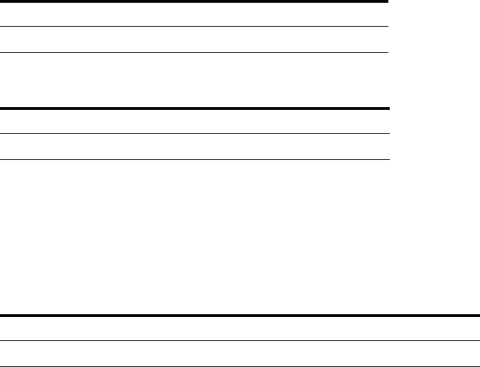
Concepts Guide 129
Expressions
14
Using Expressions
To filter empty fields
Sometimes, you may want to know if a data field contains a value or is empty.
For example, you only want to display fields that are not empty. Empty data
fields are not always actually empty; sometimes they contain a certain kind of
null information. Therefore, it is advisable to use a special syntax to filter for
fields with actual content.
To exclude empty strings, use the following expression:
To exclude empty numbers, use one of the following expressions:
To filter for date and time
When filtering for a date or date range, you must enclose the date in hash
marks:
Tab le 16 Expression for excluding empty strings
Expression Operation Value
=fieldname <> "" = =True
Expression Operation Value
=fieldname > =0
Tab le 17 Filtering for a date
Expression Operation Value
=Injection_AcquiredDate >= =#01/25/2007#
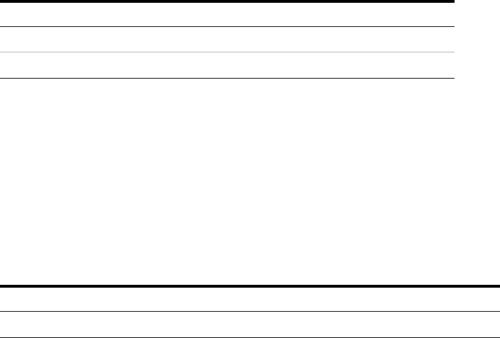
130 Concepts Guide
14
Expressions
Using Expressions
If you do not provide a specific time of day, the system assumes the time
#0:00:00#. Therefore, in order to filter for one entire day, you must filter for a
date range as follows.
It is not possible to filter for a time without using the date.
To filter for similar names
If you have different samples in a sequence, and the samples names differ only
by a number (for example, "Sample 1", "Sample 2", "Sample 3" etc.), you can
filter for those similar sample names using the Contains operator together with
wildcards:
This filter returns all samples that contain "Sample" in their name.
The following wildcards are available:
• ? matches any single character.
• * matches any number of adjacent characters.
Tab le 18 Filtering for a date (single day)
Expression Operation Value
=Injection_AcquiredDate >= 01/25/2007
=Injection_AcquiredDate < 01/26/2007
Expression Operation Value
=Sample_Name Contains ="*Sample*"
Concepts Guide 131
Expressions
14
Using Expressions
To format a date or time value
To show the date or time value in a specific format, use the Format function in
combination with format codes (“Format Codes” on page 124).
Examples:
• Show a date in the format "Monday, August 3":
=Format(Injection_AcquiredDate,"dddd, MMM d")
• Add the GMT time offset information to a date, in the format "05/05/2015
3:50:00 AM GMT+2:00":
=Injection_AcquiredDate & " GMT" &
Format(Injection_AcquiredDate,"zzz")
• Show the date in ISO-8601 standard format:
=Format(Injection_AcquiredDate,"yyyy-MM-dd HH:mm:sszzz")
This format is recommended in a compliant environment. It shows the date
and time unambiguously for all time zones in the world.
To repeat on sample names beginning with
You can repeat composite groups not only on specific data fields but also on
customized expressions. Using expressions you can, for example, repeat the
composite group on the first part of a sample name. Let's say that a sequence
contains the following samples:
• Sample1_a
• Sample1_b
• Sample1_c
• Sample2_a
• Sample2_b
• Sample2_c
Now let's say you want to repeat the composite group only two times, that is,
for Sample1 and Sample2. The first part of the expression must therefore call
the Split function, that divides the sample name in two parts, using the
underscore as a delimiter:
=Split(Sample_Name, "_")
132 Concepts Guide
14
Expressions
Using Expressions
The result of this function is a list containing the following subentries:
• Sample1; a
• Sample1; b
• Sample1; c
• Sample2; a
• Sample2; b
• Sample2; c
The next part of the expression must be a Choose function that always returns
the first element of a list:
Choose(1, [list] )
The list in this example is returned by the Split function:
=Choose(1, Split(Sample_Name, "_"))
This expression returns the following results:
• Sample1
• Sample1
• Sample1
• Sample2
• Sample2
• Sample2
If you use this expression to repeat the composite group, you will get only two
composite groups, as there are only two distinct values.
Concepts Guide 133
Expressions
14
Using Expressions
To show only part of a value
Depending on the value of a data field, you may want to show only part of the
value.
For example, the data fields Sample_DilutionFactor and Sample_Multipliers show
five numbers separated by semicolon, but only part of the numbers may be set
by the chromatographic data system. Therefore the value may look like 10; 0;
0; 0; 0 if only the first number is set. To display only the number 10 instead of
the entire string, you can use the following expression:
=Choose(1, Split(Sample_Multipliers, ";"))
• The Split function divides the string in several parts, using the semicolon as
a delimiter. In this example, the different parts are the single numbers.
• The Choose function selects and returns a specific value from a list of
values. In this example, it returns the first value, that is, the number 10.
Relative Standard Deviation
No single function returns the value for the relative standard deviation. If you
need to display this value, you must calculate it using the following
expression:
=(StDev(fieldname)/Avg(fieldname)*100)
To show the type of injection
In analytical data generated by Agilent ChemStation as a source system, the
field Injection_Volume may contain positive or negative values:
• Positive values represent the actually injected sample volume.
• Negative values represent several special injection actions. The following
values are used:
• -1: no injection
• -2: manual injection
• -3: injector program
• -4: external injector
134 Concepts Guide
14
Expressions
Using Expressions
To display either the actually injected volume or the appropriate description,
you can use the following expression:
=Iif(Injection_Volume >= 0, CStr(Round(Injection_Volume, 4)) & " " &
Injection_VolumeUnit, choose( Int(Abs(Injection_Volume)), "no injection",
"manual injection", "injector program", "external injector"))
If the original value is positive, it is only rounded off to four decimals. If it is
negative, the Int, Abs, and Choose functions are applied.
The Abs function removes the algebraic sign. Thus, negative numbers are
transformed to positive numbers. Positive numbers are left unchanged.
The Int function transforms double-precision floating-point numbers to
integer values. It returns the number in front of the decimal point (obtained by
truncating, not by rounding).
The Choose function selects and returns a value from a list of arguments. The
first parameter is a number that indicates the relevant value. In the example
above, the Choose function returns “no injection” if its first parameter is 1.
To show the sequence line number
Relevant for data acquired by OpenLAB CDS ChemStation Edition C.01.06 or
higher:
If you analyze a sequence, you can report the sequence line numbers, sample
numbers, and injection numbers. Use the following fields in your template:
• Sample_AcquisitionOrderNo: Running sequence line number at the acquisition
time. This is the preferred value in most cases.
•Sample_OrderNo: First sequence line number for a sample at the acquisition
time. If a sequence template specifies multiple injections for a line, this
field shows the sequence line number of the first injection, at the
acquisition time. It shows the same number for all of these injections in the
report.
• Injection_OrderNo: Order number of the injection if a sample got injected
multiple times. Starts with 1.
To illustrate the different fields and their meanings, see the following
examples:
• “Example with multiple injections” on page 135
• “Example with cyclic calibration” on page 136

Concepts Guide 135
Expressions
14
Using Expressions
Example with multiple injections
Tab le 19 Sequence template
Sequence line nr. Sample type Inj/Vial
1Blank1
2Cal. Std.1
3Sample A2
4Sample B2
5Cal. Std.1
6Blank1
Tab le 20 Items in the Run Queue
#Type
1Blank
2Cal. Std.
3 Sample A
4 Sample A
5 Sample B
6 Sample B
7Cal. Std.
8Blank

136 Concepts Guide
14
Expressions
Using Expressions
Example with cyclic calibration
Description In this example, the calibration standard (A) is run two times before each
sample block. A sample block can contain up to three samples. As both
samples are run two times each, the last run of Sample 2 is therefore preceded
by another calibration cycle.
The Sample_OrderNo for the last run of Sample 2 is still 6, as this was the
sequence line number of the first injection of Sample 2.
Sequence
template, run
queue, and report
Tab le 21 Numbers shown in the report
Sample type Sample_Acq
uisitionOrder
No
Sample_Orde
rNo
Sample_Num
berOfInjectio
ns
Injection_Ac
quisitionOrde
rNo
Injection_Or
derNo
Blank11111
Cal. Std.22111
Sample A 33211
Sample A 43222
Sample B 55211
Sample B 65222
Cal. Std.77111
Blank88111
Tab le 22 Sequence template
Sequence line nr. Sample type Inj/Vial Cal Interval
1Cal. Std. (A)23
2Cal. Std. (B)1
3Sample 12
4Sample 22
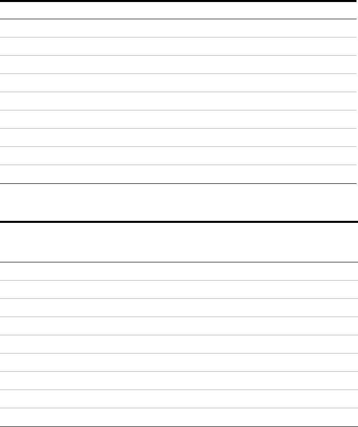
Concepts Guide 137
Expressions
14
Using Expressions
Tab le 23 Items in the Run Queue
#Type
1Cal. Std. (B)
2Cal. Std. (A)
3Cal. Std. (A)
4Sample 1
5Sample 1
6Sample 2
7Cal. Std. (A)
8Cal. Std. (A)
9Sample 2
Tab le 24 Numbers shown in the report
Sample type Sample_Acq
uisitionOrder
No
Sample_Orde
rNo
Sample_Num
berOfInjectio
ns
Injection_Ac
quisitionOrde
rNo
Injection_Or
derNo
Cal. Std. (B)11111
Cal. Std. (A)22211
Cal. Std. (A)32222
Sample 144211
Sample 154222
Sample 2 6 6211
Cal. Std. (A)77211
Cal. Std. (A)87222
Sample 2 9 6 222
138 Concepts Guide
14
Expressions
Using Expressions

139
Concepts Guide
Agilent Technologies
15
Calculation Variables
About Variables 140
Variable 141
Aggregator 141
Category Aggregator 143
Custom Extractor 145
Using Variables 146
To activate the use of variables 146
To create a variable based on summary calculation 146
To use a variable 147
To rename a variable 148
To use a variable with a unique key 149
To use an Aggregator 150
To use a Category Aggregator 152
To create an Aggregator based on a condition 153
To use a Custom Extractor 153
To find out the available keys for a complex custom field 155
To clear a variable 155
This chapter describes the characteristics and usage of calculation variables in
RTE.
140 Concepts Guide
15
Calculation Variables
About Variables
About Variables
With calculation variables, you can create a large variety of customized
reports. Calculation variables offer you the possibility to store specific values
or expression results under a specific name, and reuse the values in other
report items in the same template.
There are different scenarios in which you can use calculation variables.
Depending on the scenario, the calculation variables are referred to as Variable,
Aggregator, Category Aggregator, or Custom Extractor:
• With Variable, you can store any single numerical value.
• With Aggregator, you can store a collection of single values.
• With Category Aggregator, you can store a collection of collections.
• With Custom Extractor, you can store the key/value pairs contained in the
XML content of a complex custom field (for example,
Injection_DiagnosticData or Sample_CustomFields).
To create a new calculation variable, you can either use the Summary
Calculations feature of a table, or create a suitable expression for a
field/table/matrix value and use the Save Expression Result As... function in the
Expression Editor.
Once you have defined the variable, you can refer to it in all subsequent report
items. You can not refer to a calculation variable in a report item preceding the
one in which the variable is defined.
You can see a list of all calculation variables that are available for the current
item in the Expression Editor under the Variables node. A list of all calculation
variables used in the entire report template can be found in the Report
Properties dialog.
The Report Properties dialog also allows you to rename existing calculation
variables. The renaming includes both the definition and all expressions
where the calculation variable is used.
See the following topics for more details on the calculation variable types.
Concepts Guide 141
Calculation Variables
15
About Variables
Variable
With Variable, you can store any single numerical value. This value is identified
by a unique name. You can provide either only a static name for the variable,
or use a dynamically generated key in addition (for example, the sample
name).
Example
The variable AvgRetTime may contain the average retention time of a specific
compound found in a specific sample.
Example with Unique Key Value
The variable AvgRetTime (Sample_Name) can be created once for each sample
in a sequence. With AvgRetTime("SSRSD1"), you can show the average
retention time in the SSRSD1 sample. If the variable is embedded in a
composite group that is repeated on the sample name, you can automatically
list the average retention times for each sample.
Aggregator
With Aggregator, you can store a collection of single values. The entire
collection is identified by a unique name. You can apply several aggregating
functions to the collection. It is not possible to select a single value from the
collection.
The Aggregator provides the following functions:
•
Sum
This function returns the sum of all values currently contained in the
collection.
•
Avg
This function returns the average of all values currently contained in the
collection.
•
Stdev
This function returns the standard deviation of all values currently
contained in the collection.
142 Concepts Guide
15
Calculation Variables
About Variables
•
Prsd
This function returns the relative standard deviation (Stdev/Avg*100) of all
values currently contained in the collection.
•
Min
This function returns the lowest value currently contained in the collection.
•
Max
This function returns the highest value currently contained in the
collection.
•
Count
This function returns the number of elements in the collection.
•
Clear
This function deletes all values from the collection. At the same time, it
returns the number of deleted values.
Example
The aggregator RetTimeSSRSD1 can contain all retention times of a compound
in different injections of the SSRSD1 sample. You can return the average
retention time with Avg(RetTimeSSRSD1), or the standard deviation with
StDev(RetTimeSSRSD1).
Example
The aggregator AvgRetTimes can contain the average retention times of the
same compound in different samples. You can return the standard deviation
on the average values with StDev(AvgRetTimes).
Concepts Guide 143
Calculation Variables
15
About Variables
Category Aggregator
With Category Aggregator, you can store a collection of collections. The entire
collection is identified by a unique name. You can apply several aggregating
functions to each of the contained collections. It is not possible to select a
single value from a specific collection.
The category aggregator provides the following functions (each function takes
into account only those values belonging to the currently active value of the
given data field):
•
Sum([Field])
This function returns the sum of all values currently contained in the
collection.
•
Avg([Field])
This function returns the average of all values currently contained in the
collection.
•
Stdev([Field])
This function returns the standard deviation of all values currently
contained in the collection.
•
Prsd([Field])
This function returns the relative standard deviation (Stdev/Avg*100) of all
values currently contained in the collection.
•
Min([Field])
This function returns the lowest value currently contained in the collection.
•
Max([Field])
This function returns the highest value currently contained in the
collection.
•
Count([Field])
This function returns the number of elements in the collection.
•
Clear([Field])
This function deletes all values from the collection. At the same time, it
returns the number of deleted values.
144 Concepts Guide
15
Calculation Variables
About Variables
Example
A sample has been injected several times. One specific compound has been
detected in each injection. For each sample, a collection of the retention times
is created. These collections are addressed via the sample name. All of those
collections are contained in a category aggregator named CatRetentionTimes.
You can return the average retention time for each sample with
Avg(CatRetentionTimes(Sample_Name)). The argument in the brackets
defines the specific category, that is, the portion of values contained in
CatRetentionTimes to which the Avg function is applied.
You may use this expression, for example, in a composite group that is
repeated on the sample name. The average retention times are then
automatically calculated and shown for each sample name.
Concepts Guide 145
Calculation Variables
15
About Variables
Custom Extractor
There are specific data fields that do not contain a single value but an entire
XML structure. This XML structure contains various key/value pairs, where
the exact keys and the values depend on the chromatography data system and
its configuration (see “Keys in Diagnostic Data” on page 183). With
CustomExtractor, you can store this XML structure. You can apply several
functions to access the single values.
The CustomExtractor provides the following functions:
•
GetValue(name)
This function returns the value stored under the given name.
•
GetNameValue(index)
This function returns a combination of key and value in the form
Key=Value. With index=0 the function returns the first key/value pair.
•
GetValueByIndex(index)
This function returns the value of the name/value pair at the given position.
The first key/value pair is indexed by 0.
•
Count
This function returns the number of key/value pairs in the XML structure.
•
Clear
This function deletes the XML structure from the Custom Extractor and
returns the number 0.
Example
You can add an invisible text field to your template with the value
=Injection_DiagnosticData. If you save this value as a Custom Extractor named
CustDiagnosticData, you can subsequently access the start pressure of a
ChemStation LC measurement via the expression:
=CustDiagnosticData(GetValue("StartPressure")).
146 Concepts Guide
15
Calculation Variables
Using Variables
Using Variables
To activate the use of variables
You can only use calculation variables if they are activated for your report
template.
1 In Report Properties, select the Calculation Variables page.
2 Select the Use Calculation Variables in Expressions check box.
3 Save your settings.
To create a variable based on summary calculation
In this example, you create a table for each compound. Each table shows the
retention time of the compound in each sample. A second column shows the
difference to the average retention time of the compound in the entire
sequence. To accomplish this, you create a composite group which contains
one hidden table and one visible table. The hidden table is used to store the
average values in a variable.
1 Make sure that variables are activated in your report template (see “To
activate the use of variables” on page 146).
2 Add the data field Fields > Compound > Name to the template.
3 Add two Compound Summary tables to the template.
4 Select all three items, and click the Group Items icon in the toolbar to
create a composite group.
5 Repeat the composite group on Compound_Name.
6 If required, filter the composite group for the main signal
(Peak_Calibrole=1).
7 Prepare the first table to store the variable.
a Remove the Repeat On setting from the table.
b In the Advanced page, clear the Visible check box.
c On the Columns page, select the RT column and click Column Properties.
Concepts Guide 147
Calculation Variables
15
Using Variables
d On the Summary Calculations page, select the Average function, and enter
VarAvgRT as the Variable Name.
e Confirm all settings.
f In the Editing Pane, resize the table so that it requires only minimal
space.
8 Prepare the second table to show the difference between retention time and
retention time average.
a Remove the Repeat On setting from the table.
b On the Columns page, add a Custom Field to the table layout.
c Move the new column to the right of the RT column and adjust its size.
d In the Column Properties of the new column, enter the following
expression as a value: =Peak_RetentionTime - VarAvgRT
e On the Format page, adjust the number format for the new column to
Number, 1234.00, and set Rounding to 4 decimal places.
f Confirm all settings and generate a preview.
The generated report will show the difference between the individual
retention times and the sequence average.
To use a variable
To create a variable:
1 Make sure that variables are activated in your report template (see “To
activate the use of variables” on page 146).
2 Add two text fields or a data fields to the template.
3 Select the two fields, and click the Group Items icon in the toolbar to create
a composite group.
4 Repeat the composite group on Sample_Name.
5 Enter a customized expression as a value for one of the fields, for example a
correction factor for the sample amount: =Sample_Amount * 99
6 Click Save Expression Result As...
The Save Expression Result As dialog opens.

148 Concepts Guide
15
Calculation Variables
Using Variables
7 Make sure that the Variable option is selected, and enter a Calculation Variable
Name, for example VarAmountCorrected.
8 Save your settings.
To use the variable in subsequent report items:
1 Resize the composite group to provide space for new report items.
2 Add a table with compound information to the composite group, for
example the Compound Results table.
3 Add a new column to the table. Enter a customized expression as a value
for the new column, for example the compound amount multiplied by the
corrected sample amount: =Compound_Amount * VarAmountCorrected
To rename a variable
1 In Report Properties, select the Calculation Variables page.
2 Select the variable you want to rename.
3 Click Rename.
The Rename Calculation Variable dialog opens.
4 Enter the new name for the variable.
5 Save your settings.
The variable is now renamed in all expressions in which it is used, in the
entire report template.
NOTE
No special characters are allowed in the variable name.

Concepts Guide 149
Calculation Variables
15
Using Variables
To use a variable with a unique key
The following example describes how to create a table that compares a
compound's retention time in each sample with the average retention time.
To prepare the variable:
1 Make sure that variables are activated in your report template (see “To
activate the use of variables” on page 146).
2 Add two text fields to the template.
3 Select the two text fields and click to create a composite group.
4 Repeat the composite group on Compound_Name.
5 In the first text field, enter a static text. For example, RT Average.
6 In the second field, enter an expression for the average retention time:
=Avg(Peak_RetentionTime)
7 Save the expression of the second field as a variable. Use the following
settings:
• Calculation Variables: Variable
• Calculation Variable Name: For example, VarRTAverage
• Unique Key Value: =Compound_Name
To use the variable:
1 Underneath the composite group, create a Compound Summary table.
2 Add a table column with the following expression: =Peak_RetentionTime -
VarRTAverage(Compound_Name)
NOTE
In the Unique Key Value setting, you must use the same value as you used for repeating
the composite group

150 Concepts Guide
15
Calculation Variables
Using Variables
To use an Aggregator
This example describes how to compare the average peak areas for two
different sets of samples (for example, calibration samples and checkout
samples, or samples with a name containing SampleA and samples with a
name containing SampleB).
To prepare the variables:
1 Add the Compound Results table two times to the template.
2 Filter the tables according to the samples for which you want to obtain the
average peak areas.
3 In each table: Open the Column Properties dialog of the Area column, and save
the value as a variable. Use the following settings:
• Calculation Variables: Aggregator
• Calculation Variable Name: For example, AreaAggregator1 in the first
table, and AreaAggregator2 in the second table.
• Category: [None]
• Condition: [None]
Tab le 25 To filter for the sample type
Expression Operation Value Description
=Sample_Type = =1 The first table
contains only
calibration samples.
=Sample_Type = =2 The second table
contains only
checkout samples.

Concepts Guide 151
Calculation Variables
15
Using Variables
To use the variables:
1 Underneath the two tables, create a text field with the following expression:
=Avg(AreaAggregator1) - Avg(AreaAggregator2)
Instead of the Avg function, you can also apply the Sum, Stdev, Prsd, Min,
Max, or Count function to the Aggregator variables.
NOTE
Clear function
If you create and use the Aggregator inside a composite group, use the Clear function at
the end of the group. Add two hidden text fields with the following expressions:
=Clear(AreaAggregator1)
=Clear(AreaAggregator2)
This clears all contents of the Aggregator, which ensures that the values are not mixed in
subsequent group repetitions.

152 Concepts Guide
15
Calculation Variables
Using Variables
To use a Category Aggregator
This example describes how to compare the average peak areas for two
different sets of samples. In contrast to the other example (see “To use an
Aggregator” on page 150), the information is now prepared and shown
separately for each compound.
To create the variables:
1 Add the Compound Results table to the template twice.
2 Repeat both tables on Compound_Name.
3 Filter the tables according to the samples for which you want to obtain the
average peak areas.
4 In each table: Open the Column Properties dialog of the Area column, and save
the value as a variable. Use the following settings:
• Calculation Variables: Aggregator
• Calculation Variable Name: For example, AreaAggregator1 in the first
table, and AreaAggregator2 in the second table.
• Category: Compound_Name
• Condition: [None]
To use the variables:
1 Underneath the tables, add two text fields to the template:
• The first text field shows some static text and the compound name:
="Difference between average areas for" + Compound_Name
• The second text field shows the calculated value:
=Avg(AreaAggregator1(Compound_Name)) -
Avg(AreaAggregator2(Compound_Name))
2 Select the two fields and create a composite group.
3 Repeat the composite group on Compound_Name.
After a number of tables, the generated template will show the text fields
for each single compound.
NOTE
For the Category setting, you must use the same value as in the Repeat On setting for the
tables.
Concepts Guide 153
Calculation Variables
15
Using Variables
To create an Aggregator based on a condition
This examples describes how to sum up only those peak areas that are greater
than a certain value. To sum up the areas per compound, a composite group is
used that is repeated on Compound_Name.
1 Add the Compound Results table to the template.
2 Open the Column Properties dialog of the Area column, and save the value as a
variable.
a Under Calculation Variables, select Aggregator.
b Under Calculation Variable Name, enter a name. For example, AreaIf.
c Under Condition, double-click Expression....
d In the Expression Editor, enter the following expression: =Peak_Area > 3
e Save your settings.
3 Underneath the table, add a text field that shows the sum of all areas that
meet the condition. Use the following condition: =Sum(AreaIf)
4 Add another text field that contains the Clear function: =Clear(AreaIf)
5 Clear the Visibility check box for the text field with the Clear function.
6 Select the table and both text fields, and create a composite group.
7 Repeat the composite group on Compound_Name.
For each compound, the generated template will show a table with all
injections, and a textbox with the sum of peak areas. The sum is based on all
peak areas greater than 3.
To use a Custom Extractor
The following example describes how to access the diagnostic data provided by
a ChemStation system.
To create a custom extractor:
1 Add a text field to the template.
2 Enter the expression =Injection_DiagnosticData as a value.
3 In the Expression Editor, click Save Expression Result As....
The Save Expression Result As dialog opens.

154 Concepts Guide
15
Calculation Variables
Using Variables
4 Make sure that the CustomExtractor option is selected, and enter a Calculation
CustomExtractor Name, for example MyDiagnosticData.
5 Save your settings.
6 Set the text field to invisible.
To use a Custom Extractor
1 Add a text field to the template, and place it underneath the text field
created before.
2 Enter the following expression to access the start pressure of an injection:
=MyDiagnosticData(GetValue("StartPressure")). You can also select the
variable and the function in the Expression Editor in the lower panels.
NOTE
No special characters are allowed in the variable name.
NOTE
In this example, you access the start pressure with the key StartPressure. See “Keys in
Diagnostic Data” on page 183 or “To find out the available keys for a complex custom
field” on page 155 for information on other available keys.
Concepts Guide 155
Calculation Variables
15
Using Variables
To find out the available keys for a complex custom field
If you are not sure which keys are available in a complex custom field, you can
use the following procedure to view the entire XML structure. The keys are
given as Name attributes of the CustomField tags.
1 Add the complex custom field (for example, the field DiagnosticData in the
Injection category) to the template.
The CustomExtractor Info dialog opens and asks you for a key name.
2 Leave the input field empty and click Cancel.
RTE adds the field to the template. The label shows the name of the field
(for example, Injection_DiagnosticData), and the value shows the XML
content.
3 Adjust the width of the field to the template width.
4 Generate a report preview to see the entire XML content.
5 Find the Name attributes. The values of these attributes are the keys that
you can use for this complex custom field.
For example: Name="StartPressure"
To clear a variable
1 Drag the snippet Special Objects > Clear Calculation Variable to the report
template.
The Clear Calculation Variable dialog opens.
2 Select the variable for which you want to clear the value.
If no variables are listed, you do not use any variables in your template.
3 Click OK.
An invisible text field is added to the template. As a value, it contains the
expression to clear the value of the variable. For example,
=Code.DVL.Clear("myVar")
The text shown in the invisible text box is simply the return code of the
clear function. As the field is invisible, nothing will be shown in the report
preview.
Below this invisible text box, the system will use the cleared value of the
variable.
156 Concepts Guide
15
Calculation Variables
Using Variables

158 Concepts Guide
16
Report Template Audit Trail
About the Report Template Audit Trail
About the Report Template Audit Trail
The Report Template Audit Trail provides a detailed list of all modifications of
a template. The list includes the following information:
•Template Version: Each time you save the template, the template version
increases by one.
•User Name: Name of the user who modified the template. The name is
provided by the operating system.
• Machine Name: Name of the PC on which the template was modified.
•Date Time: Date and time when the template version was saved.
•Audit Entry: Description of the modification.
The modifications are written to the Report Template Audit Trail when you
save the report template. Thus, the Report Template Audit Trail shows all
changes up to the last saving date.

159
Concepts Guide
Agilent Technologies
17
Report Parameters
About Report Parameters 160
Using Report Parameters 161
To create a single report parameter 161
To create a multi-value report parameter 162
To calculate with a report parameter 163
To filter for a single report parameter 164
To filter for a multi-value report parameter 164
This chapter describes the characteristics and usage of report parameters in
RTE.
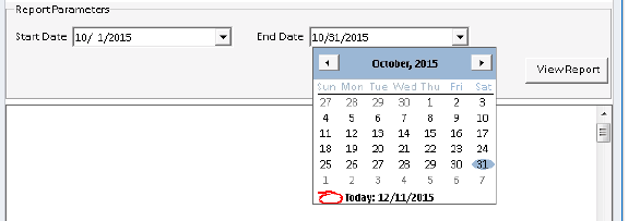
160 Concepts Guide
17
Report Parameters
About Report Parameters
About Report Parameters
Using report parameters lets you create dynamic report templates. There are
two basic types of parameters:
• Interactive report parameters (default):
You need to provide these parameters each time before the report is
generated. An additional report parameter pane is shown at the top of the
report preview area, where you can enter the required values. When you
click View Report, the report is generated using the given parameters.
Figure 21 Report parameters example
Interactive parameters can be, for example:
• Start date
• End date
• Year
• Compound name
• Peak area (to filter a peak results table)
• Internal report parameters:
There is no input field for these parameters in the report preview. You set
the parameter to a fixed value when you develop the template. The report is
automatically generated using the given values.
Examples for internal parameters are:
• Correction factors that you use in several expressions
• Amount values that you use in conditional formatting
You can then use the value from a report parameter in almost any expression
in the entire template. The only exception are filters for the graphical objects
(chromatograms, calibration curves, spectra, charts), which do not
expressions with report parameters yet.

Concepts Guide 161
Report Parameters
17
Using Report Parameters
Using Report Parameters
To create a single report parameter
This procedure explains how to create a simple report parameter with only
one single value.
1 In Report Properties, select the Report Parameters page.
2 Click Add.
A new parameter is created and added to the list.
3 Adjust the parameter name. For example, enter Correction Factor.
4 Adjust the data type. For example, select Integer
5 In the field Prompt name, provide a label for the report parameter. For
example, enter Correction Factor:.
This text will be shown in the report parameter pane at the top of the
preview area, where users provide the required values for the report
parameters.
6 If required, select the Internal check box.
• To create an interactive report parameter: Ensure that the check box is
cleared.
When you preview the report, you will have to provide a value before you
can generate the report.
• To create an internal report parameter: Select the check box.
For internal report parameters, no input field will be shown in the report
preview. The report is automatically generated using the default value.
7 Optional: Provide several labels and values under Available Values. To
simplify matters, use the same entries for Label and Value.
If you provide several available values, their labels will be shown as a
drop-down list where only one single value can be selected.

162 Concepts Guide
17
Report Parameters
Using Report Parameters
8 Provide a default value for the report parameter.
For interactive report parameters, the default parameter will be shown as a
suggested value in the report preview. For internal report parameters, and
also if the template is used in the context of an automated sequence run,
the system will automatically access this default value.
To create a multi-value report parameter
1 Create a new report parameter, and provide the information for Parameter
name, Data type and Prompt name.
2 Under Available Values, enter the values that you want to offer to the user.
The labels will be shown in the user interface, the values will be used by the
report when you calculate with the report parameter.
3 Select the Multi-Value check box.
The available values will be shown as list of check boxes in the report
preview.
4 Enter one or more default values.
The default value must correspond to one of the available values. You can
provide multiple default values. In this case, multiple check boxes will be
selected by default.
Concepts Guide 163
Report Parameters
17
Using Report Parameters
To calculate with a report parameter
Report parameters provided either internally or interactively can be used for
customized calculations. The way report parameters are referenced in
expressions depends on the parameter type (single-value or multi-value).
Single-value report parameter
Syntax: =<ParameterName>
Example:
Your report contains a table with peak results. You want to offer the
possibility to multiply the results by a correction factor.
1 In the Report Parameters dialog, create a single report parameter named
CorrectionFactor with the data type Integer and the default value 1.
2 In the table, enter the following expression in the Value field for the column:
=Compound_Amount * CorrectionFactor
This syntax is valid as long as the Multi-Value check box is cleared. Even if you
enter several values under Available Values, the user can only select one of
these values, and the expression is unambiguous.
Multi-Value report parameter
If you have selected the Multi-Value check box, all selected values will be stored
in a collection. Therefore, you must add an index to the parameter name to
refer to a specific value.
Syntax: =<ParameterName>(<index>)
Example:
For a multi-value report parameter named MyPara, use the following:
• =MyPara(0) to refer to the first selected value
• =MyPara(1) to refer to the second selected value
• ... etc.

164 Concepts Guide
17
Report Parameters
Using Report Parameters
To filter for a single report parameter
For example, you want to use a report parameter to filter for peak areas.
In the Report Parameters dialog, you create a report parameter named
Report_Parameter_0 with the data type Float and the default value 0.5.
To filter for peak areas that are greater than the value of the report parameter,
use the following filter settings:
If you generate the report, you can enter a value for Report_Parameter_0. The
results are filtered for peak areas greater than or equal to the given value.
To filter for a multi-value report parameter
If you use multi-value report parameters, you may want to filter for multiple
values at the same time. For example, you have create the report parameter
STypes for sample types, and provide the following available values:
Expression Operation Value
=Peak_Area >= =Report_Parameter_0
Label Value
Calibration 1
Sample 3
Control 4

Concepts Guide 165
Report Parameters
17
Using Report Parameters
If the user selects multiple values, you want to show a table for all selected
values. To achieve this, you can use the following filter expression for the
table:
The Join function returns a string, created by concatenating the elements of
an array.In this example, the array is the multi-value report parameter
STypes. The second parameter of the Join function (in this example, a space "
") is the delimiter to be used when creating the string.
The Contains function returns true, if the preceding string contains the
characters given as a parameter to the Contains function.
Expression Operation Value
=Join(STypes, "
").Contains(Sample_Type)
==True
166 Concepts Guide
17
Report Parameters
Using Report Parameters

167
Concepts Guide
Agilent Technologies
18
Advanced Report Features
Document Map 168
About Document Map 168
Using Document Map 169
Locked/Unlocked Report Items 171
About locked/unlocked report items 171
To lock or unlock report items 172
Custom Assemblies 173
To add a custom assembly 173
To use code from a custom assembly 174
This chapter describes the characteristics and usage of advanced report
features such as document maps, locked report items , or custom assemblies.
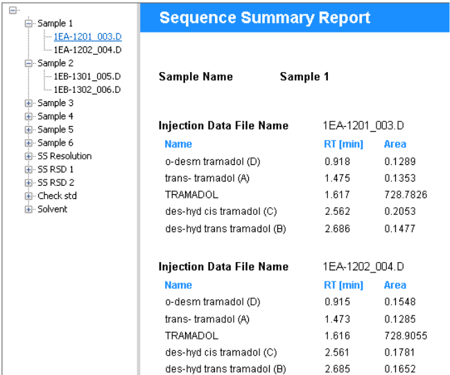
168 Concepts Guide
18
Advanced Report Features
Document Map
Document Map
About Document Map
The document map offers you a list of bookmarks in the report preview. With
these bookmarks, you can easily jump to the page in the report that contains
the corresponding information. For example, the report contains a sequence
with 20 samples. Each sample has been injected several times, and for each
injection there is a results table. With the bookmarks in the document map,
you can directly jump to each specific injection.
Concepts Guide 169
Advanced Report Features
18
Document Map
You can create bookmarks for repeated tables or matrices: With these report
items, the document map expression is always the same as the repeat-on
expression.
In addition, you can specify bookmarks for other report items, such as text
fields or data fields, inside a repeated composite group. In most cases the
bookmark will reflect the value that you used to repeat the composite group.
However, you can also customize this expression according to your
requirements.
When you export a report to PDF that contains a document map, the
bookmarks will be available in PDF as well.
Using Document Map
This example describes a sequence with several samples. Each sample has
been injected several times. The document map shows a bookmark for each
injection.
1 Create a new Single Sequence Summary template.
2 Add the following report items to your template and place them under each
other:
a The Sample_Name data field
b The Injection_DataFileName data field
c The Compound Results table
3 Select the Compound Results table and the Injection_DataFileName field, and
click the Group Items icon to create a composite group containing these two
items.
4 Repeat the group on =Injection_ID.
5 Select the composite group and the Sample_Name data field, and click the
Group Items icon in the toolbar to create another, superordinate composite
group.
6 Repeat the superordinate composite group on =Sample_Name.
7 Set the document map expression for the Sample_Name data field to
=Sample_Name.
8 Set the document map expression for the Injection_DataFileName field to
=Injection_DataFileName.

170 Concepts Guide
18
Advanced Report Features
Document Map
9 In the report preview, click on the Plus icon to expand the document map.

Concepts Guide 171
Advanced Report Features
18
Locked/Unlocked Report Items
Locked/Unlocked Report Items
About locked/unlocked report items
You can lock either single report items or composite groups containing
multiple report items. A locked item is protected against any modification.
What is possible with a locked item:
• View properties.
• Move the item inside the template.
What is impossible with a locked item:
• Modify properties.
• Remove the item from the template.
For example, you can lock a composite group containing complex calculations
that have been validated and approved. With the lock, you make sure that the
items are not changed by accident.
NOTE
You can only lock or unlock items if you have the Lock/unlock report item privilege.
Privileges are configured in the Control Panel.

172 Concepts Guide
18
Advanced Report Features
Locked/Unlocked Report Items
To lock or unlock report items
Prerequisites
To be able to carry out the procedure as described, you need the corresponding privileges.
Privileges are configured in the Control Panel.
1 Select the report item.
If the item is locked, a small red lock icon is shown in the top left corner of
the selection border.
2 To unlock a locked item: Right-click the item and select Unlock from the
context menu. Alternatively, you can click the Unlock Report Item icon in the
toolbar.
3 To lock an item: Right-click the item and select Lock from the context menu.
Alternatively, you can click the Lock Report Item icon in the toolbar.

Concepts Guide 173
Advanced Report Features
18
Custom Assemblies
Custom Assemblies
With custom assemblies, you can add your own programming to the report
template. You can program specific classes and methods to enhance the
functions in the Expression Editor with your own functions.
You can add custom assemblies in the Report Properties dialog. There you
specifiy the class names and instance names. You can use these instances and
their methods in the Expression Editor. In the Expression Editor, these
classes and instances are listed under the Custom Classes category.
To add a custom assembly
1 Open the Report Properties dialog.
2 In Report Properties, select the Custom Assemblies page.
3 Click to navigate to the custom assembly.
4 Click Open to add the selected assembly.
5 Under Classes and Instances: Enter the fully qualified class name of the class
you want to use, and specify a unique instance name to be used in the
report template.
NOTE
The custom assembly must be located in the same folder as the application executables
for the Report Template Editor (e.g. IntelligentReporting.RenderServiceHost.exe).
174 Concepts Guide
18
Advanced Report Features
Custom Assemblies
To use code from a custom assembly
1 In the Expression Editor, expand the Custom Classes category, and select the
class you want to use.
2 In the lower middle panel, select the instance of the class you want to use.
All methods provided by the class are listed in the lower right panel.
3 Double-click the method to insert it into your expression.
For example, if there is the instance Obj with the method myMethod, the
code Obj.myMethod will be added to your code in the Expression Editor.

175
Concepts Guide
Agilent Technologies
19
Appendix
Enumerations 176
Peak_BaselineModel enumeration 176
Sequence_DABracketingMode enumeration 177
Peak_CalibRole enumeration 177
CalibCurve_Origin enumeration 177
CalibCurve_Type enumeration 178
Compound_QuantitationType enumeration 178
Compound_Type enumeration 179
Sample_InjectorPosition enumeration 179
Instrument_Technique enumeration 179
Peak_Type enumeration 180
Injection_DAMethodQuantitationType enumeration[ 181
Sample_Type enumeration 182
Keys in Diagnostic Data 183
This chapter contains a list of all operators and functions available in the
Expression Editor.

176 Concepts Guide
19
Appendix
Enumerations
Enumerations
Some data fields contain specific numbers that stand for certain values. These
enumerations typically represent all data that is shown in a drop-down list in
your chromatography data system.
Display enumerations
If you add an enumaration data field by dragging it from the Report Items
browser > Fields node to the report template, the application automatically
creates an expression to show the text value corresponding to the stored
number. Also if you use the prepared table or matrix snippets, they show the
corresponding text.
If you add the database field directly in the Expression Editor, use the
Choose
function to show the text value (see Table 5 on page 118). For
example:
=Choose(First(CalibCurve_Origin )+1 , "Ignore", "Include", "Force",
"Connect")
Note that the first argument is addressed with the number "1", not with "0".
Filter for enumerations
If you want to filter for a specific value of an enumeration, you must enter the
correct number in the Value field. The following sections you find the text list
values and corresponding numbers of all enumerations.
Peak_BaselineModel enumeration
Number Description
0Unknown
1Linear
2Exponential
3 ExtendedExponential

Concepts Guide 177
Appendix
19
Enumerations
Sequence_DABracketingMode enumeration
Peak_CalibRole enumeration
CalibCurve_Origin enumeration
Number Description
0None
1Standard
2 StandardClearCalibration
3 StandardOverlap
4 OverallSequence
5 SequenceBackCalculation
Number Description
0None
1Main
2 Qualifier
3Ignore
4NewMain
5NewIgnore
6 DetectorMain
Number Description
0Undefined
1Include
2 Force
3 Connect

178 Concepts Guide
19
Appendix
Enumerations
CalibCurve_Type enumeration
Compound_QuantitationType enumeration
Number Description
0Undefined
1Linear
2Quadratic
3Cubic
4Exponential
5Logarithmic
6Power
7AverageRF
8Piecewise
9Custom
10 LogLog
Number Description
0Undefined
1Area
2Height
3 Count
4AreaPerc
5HeightPerc
6LogArea
7LogHeight
8CustomExpression

Concepts Guide 179
Appendix
19
Enumerations
Compound_Type enumeration
Sample_InjectorPosition enumeration
Instrument_Technique enumeration
Number Description
0Unknown
1Expected
2 UncalibratedExpected
3PeakSum
4Group
5 NotIdentifiedExpected
6 ManuallyIdentifiedExpected
7 ManuallyUnidentifiedExpected
Number Description
0Undefined
1Front
2Back
Number Description
0Undefined
1 LiquidChromatography
2 GasChromatography
3 MassSpectrometry
4 CapillaryElectrophoresis
5UVVis
6MicroFluidics

180 Concepts Guide
19
Appendix
Enumerations
Peak_Type enumeration
Number Description
0Unknown
1Tangent
2Solvent
3AreaSum
4 FrontShoulderDropLine
5FrontShoulderTangent
6Manual
7 ManualNegative
8 ManualNegativeShoulderDropLine
9 ManualNegativeShoulderTangent
10 ManualShoulderDropLine
11 ManualShoulderTangent
12 ManualTangentSkimExpo
13 ManualTangentSkimNewExpo
14 ManualTangentSkimNormal
15 Negative
16 NegativeShoulderDropLine
17 NegativeShoulderTangent
18 NormalPeak
19 RearShoulderDropLine
20 RearShoulderTangent
21 ReCalcSolventPeak
22 ShoulderDropLine
23 ShoulderTangent
24 TangentSkimExpo
25 TangentSkimNewExpo
26 TangentSkimNormal

Concepts Guide 181
Appendix
19
Enumerations
Injection_DAMethodQuantitationType enumeration[
Name Description
0Undefined
1Area%
2ESTD
3 ESTD% (only populated for imported
ChemStation data)
4Height%
5ISTD
6 ISTD% (only populated for imported
ChemStation data)
7Norm%
NOTE
To report whether mass % is calculated, use the Single Data Analysis Method Parameter
snippet and select the value Method Parameters > Compound Parmeters > Calculate
mass % (“Add a single method parameter” on page 108).

182 Concepts Guide
19
Appendix
Enumerations
Sample_Type enumeration
Number Description
0Unspecified
1 Calibration
2 Checkout
3Sample
4Control
5Blank
6Ladder
7 SystemSuitability
8 CalibrationCheck
9DoubleBlank
10 Matrix
11 MatrixDup
12 MatrixBlank
13 TuneCheck
14 ResponseCheck
15 Spike

Concepts Guide 183
Appendix
19
Keys in Diagnostic Data
Keys in Diagnostic Data
Keys in the Injection_DiagnosticData field
The keys used in the Injection_DiagnosticData field depend on the generator that
created the data. They may include Early Maintenance Feedback (EMF)
counters such as the number of hours of the detector lamp.
The following table shows the most common keys according to the generator
used.
NOTE
If you are not sure about the correct keys, see “To find out the available keys for a complex
custom field” on page 155.
ChemStation ChemStore
DAD1UVOnTime n/a
DAD1UVBurnTime n/a
DADVisOnTime n/a
DAD1VisBurnTime n/a
StartPressure BegPumpPres
StopPressure EndPumpPres
StartFlow BegPumpFlow
StopFlow EndPumpFlow
PumpType n/a
StartLeftTemp BegLTemp
StopLeftTemp EndLTemp
S tar tR ig ht Tem p B eg R Tem p
StopRightTemp EndRTemp
AirTemp n/a
InjVolume n/a
ActInjVolume n/a
InjVolumeText n/a
ActInjVolumeText n/a

©
Agilent Technologies 2009-2017
Printed in Germany
09/2017
*M8305-90023*
*M8305-90023*
M8305-90023
www.agilent.com
Agilent Technologies
In This Book
This guide contains information for template
developers. It describes the concepts and
advanced features of the Report Template
Editor (RTE).
