
Comfosystems
ComfoWell installation instructions
Cooling Fresh Air
Clean Air
Heating

External wall
grille
CA 350
ventilation unit
ComfoPipe
Attenuator
Attenuator
The ComfoWell system
Installation instructions

Filter box
Spacer frame
Manifold
Manifold flat 51
Mounting plate
ComfoWell Series 220 system 2
ComfoWell Series 320 system 12
ComfoWell Series 520 system 26

2
ComfoWell Series 220 system
Installation example
Individual
Composite
On unit
Installation example

3
ComfoWell Series 220 system
Accessories
Accessories
Product Description
Width 220 up to 4 ComfoTubes
Attenuator CW-S-220
990 323 500
End piece CW-P 220-DN125
990 323 510
Installation set CW-K 220-CA140
990 323 515
Mounting plate
CW-M 220-4xCT 75
990 323 520
Mounting plate
CW-M 220-4xCT 90
990 323 521
Manifold CW-D 220
990 323 530
Product Description
Filter housing CW-F 220
990 323 550
Replacement filter F7 for filter
housing CW-F 220
990 323 600
Replacement filter F9 for filter
housing CW-F 220, 2 pcs.
990 323 601
Replacement activated charcoal
filter for filter housing CW-F 220
990 323 602
Spacer frame
990 323 534

44
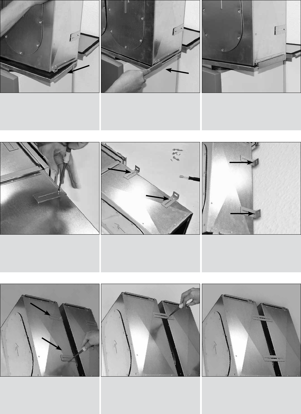
Installation sequence
1. Fit ComfoWell together
1. Unscrew the mounting
brackets
2. Make all connections using
the clamping rail
2. Rotate and secure mounting
brackets
3. OK
3. Secure the element to the
wall
Securing
ComfoWell CW 220
Installation sequence

5Installation options
1. Mounting plate
4. End piece
2. Filter housing (correct) 3. Do not install filter housing
with the opening pointing
downwards (incorrect)
5. Manifold
ComfoWell CW 220
Installation options

6
Filter installation
1. Undo screws
4. Close cover and tighten
screws
2. Open cover 3. Install filter
ComfoWell CW 220
Filter installation

7Filter installation
1. Undo screws
4. Attach clamping rail
7. Install filter
2. Open cover and unscrew
clamping rail on cover
5. Unscrew clamping rail from
housing bottom
8. Close cover and tighten
screws
3. Rotate clamping rail
6. Rotate and secure
ComfoWell CW 220 activated charcoal
Filter installation

8
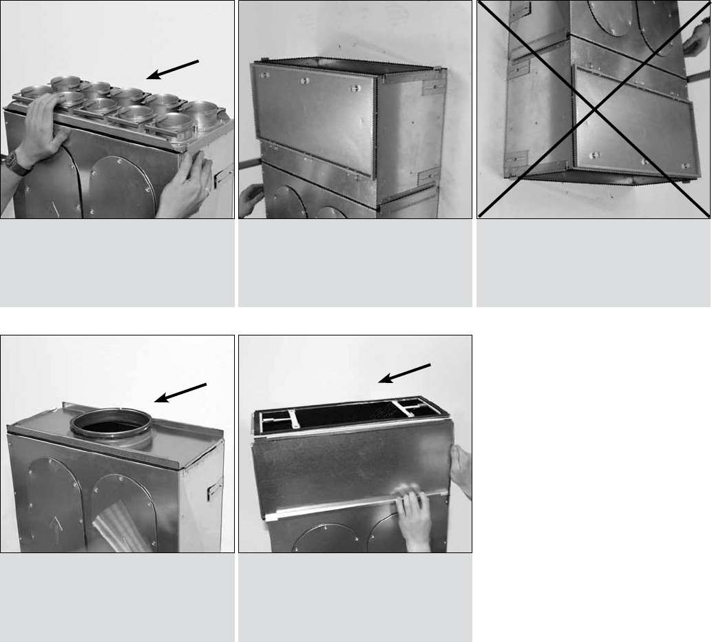
Manifold conversion
1.
4. Remove cover
7. OK
2. Pull off clamping rail
5. OK
8. Fit either mounting plate or
distance frame
3. OK
6. Rotate manifold
ComfoWell CW 220
Manifold conversion

9Installing the manifold under the ceiling
1. Screw the threaded rods into
the mounting plate
4. Push manifold onto the
threaded rods until the
manifold locks in place
2. OK
5. Secure manifold using
M6nuts
3. Use spacer frame as
required (to compensate for
irregularities)
6. Tighten all nuts with a
6mm socket
ComfoWell CW 220
Installing the manifold under the ceiling

1010
Installation sequence
1. CA 140 installation set
4. Mount ComfoWell on the
end plate
2. Attach end plate to CA 140 3. Tighten clamping ring
ComfoWell CW 220 and CA 140
Installation sequence

11Attenuator inspection opening
1. Undo screws 2. Carefully pull out the core
element
ComfoWell CW 220 and CA 140
Attenuator inspection opening

12
Installation example
ComfoWell Series 320 system
Installation example
Individual
Composite
On unit

13Installation example
ComfoWell Series 320 system
Installation example
On unit CA 200
On unit CA 350
On unit CA 140

14
Accessories
ComfoWell Series 320 system
Accessories
Product Description
Width 320 up to 6 ComfoTubes
Attenuator CW-S 320
990 323 501
Attenuator with fixed endplates
CW-SF 320
990 323 503
End piece CW-P 320-DN125
990 323 511
End piece reduced
CW-P 320-DN150
990 323 562
End piece CW-P 320-DN160
990 323 512
End piece CW-P 320-DN180
990 323 527
Mounting set CW-K 320 CA 140
990 323 516
Mounting set CW-K 320 CA 200
990 323 517
Product Description
Mounting plate CW-M 320-6xCT 75
990 323 516
Mounting plate CW-M 320-6xCT 90
990 323 523
Spacer frame
990 323 535
Mounting set for 2 attenuators, width
320 on unit with 1 pair eccentric
sleeves for min. overall width,
1U-profile 1 + support CW-K 320-
CA350
990 323 526
Filter housing CW-F 320
990 323 551
Replacement filter F7 for filter
housing CW-F 320, 2 pcs.
990 323 603
Replacement filter F9 for filter
housing CW-F 320, 2 pcs.
990 323 604
Replacement activated charcoal
filter for filter housing CW-F 320,
2 pcs.
990 323 605

15Installation sequence
1. Fit ComfoWell together 2. Make all connections using
the clamping rail
3. OK
ComfoWell CW 320
Installation sequence
1. Unscrew the mounting
brackets
2. Rotate and secure mounting
brackets
3. Secure the element to
thewall
Attaching to the wall

16
Joining together
1.
1c. OK
2b. Screw on second fastening
sheet
1a. Unscrew the mounting
brackets
2. Screw on fastening sheet
1b.
2a. OK
ComfoWell CW 320
Joining together

17Installation options
1. Mounting plate
4. End piece
2. Filter housing
5. Manifold
3. Wrong
Do not install with the
opening pointing downwards
ComfoWell CW 320
Installation options

18
Filter installation
1. Undo screws
4. Close cover and tighten
screws
2. Open cover 3. Install filter
ComfoWell CW 320
Filter installation

19Installation
1. Undo screws
4. Attach clamping rail
7. Install filter
2. Open cover and unscrew
clamping rail on cover
5. Unscrew clamping rail from
housing bottom
8. Close cover and tighten
screws
3. Rotate clamping rail
6. Rotate and secure
ComfoWell CW 320 activated charcoal filter
Installation

20
Manifold conversion
4. Remove cover
7. OK
2. Pull off clamping rail
5. OK
8. Fit either mounting plate or
distance frame
3. OK
6. Rotate manifold
ComfoWell CW 320
Manifold conversion

21Installation
1. Screw the threaded rods into
the mounting plate
4. Push manifold onto the
threaded rods until the
manifold locks in place
2. OK 3. Push the spacer frame
onto the threaded rods
ComfoWell CW 320
Installing the manifold under the ceiling using the spacer frame
5. Secure manifold using
M6nuts
6. Tighten all nuts with a 6 mm
socket
1. Undo screws 2. Carefully pull out the core
element
CW 320 attenuator inspection opening

22
Installation
1. CW-K 320 installation set
CA 140
4. Mount ComfoWell on the
end plate
2. Attach end plate to CA 140 3. Tighten clamping ring
ComfoWell CW 320 and CA 140
Installation sequence

23Installation sequence
1. CW-K 320 installation set
CA 200
4. Place attenuator on the end
plate
2. Attach end plate to CA 200 3.
ComfoWell CW 320 and CA 200
Installation sequence

24
Installation sequence
1. CW-K 320 installation set
CA 350
5. OK
2. Unscrew screws approx.
3mm out of the CA 350
4. Attach the mountings to the
U-profile
6. Insert the 160 mm nipple into
the CA 350
3. Locate U-profile and screw
onto the CA 350
ComfoWell CW 320 and CA 350
Installation sequence
7. Mount end piece plate 9. Place ComfoWell on the end
plate
8. Secure two end piece plates
with one screw each

25Notes
Notes

26
Installation example
ComfoWell Series 520 system
Installation example
Composite
Individual

27
On unit CA 350
Installation example
ComfoWell Series 520 system
Installation example
On unit CA 550

28
Accessories
ComfoWell Series 520 system
Accessories
Product Description
Attenuator CW-S-520
990 323 502
End piece CW-P 520-DN200
990 323 514
End piece reduced
CW-P 520-DN180
990 323 513
End piece reduced
CW-P 520-DIN160
990 323 518
Mounting set CW-K 520-CA350
990 323 518
Mounting set CW-K 520-CA 550
990 323 519
Mounting plate
CW-M 520-10x CT 75
990 323 524
Product Description
Mounting plate
CW-M 520-10xCT 90
990 323 525
Manifold CW-D 520
990 323 532
Spacer frame CW 520
990 323 536
Filter housing CW-F 520
990 323 552
Replacement filter F9 for filter
housing CW-F 520, 2 pcs.
990 323 606
Replacement filter F7 for filter
housing CW-F 520, 2 pcs.
990 323 607
Replacement activated charcoal
filter for filter housing CW-F 520,
2pcs.
990 323 608
29Installation sequence
1. Fit ComfoWell together
1. Unscrew the mounting
brackets
2. Make all connections using
the clamping rail
2. Rotate and secure mounting
brackets
3. OK
3. Secure the element to
thewall
Securing
ComfoWell CW 520
Installation sequence
1a. Screw on fastening sheet1. Unscrew the mounting
brackets
Joining together
1b. OK
30
Installation options
1. Mounting plate
4. End piece
2. Filter housing
5. Manifold
3. Wrong
Do not install with the opening
pointing downwards
ComfoWell CW 520
Installation options

31Filter installation
1. Undo screws
4. Close cover and tighten
screws
2. Open cover 3. Install filter
ComfoWell CW 520
Filter installation

32
Installation
1. Undo screws
4. Attach clamping rail
7. Install filter
2. Open cover and unscrew
clamping rail on cover
5. Unscrew clamping rail from
housing bottom
8. Close cover and tighten
screws
3. Rotate clamping rail
6. Rotate and secure
ComfoWell CW 520 activated charcoal filter
Installation

33Manifold conversion
1. Pull off clamping rails
4. Rotate
2. Remove cover
5.
3. Pull off clamping rail
6. Fit either mounting plate or
distance frame
ComfoWell CW 520
Manifold conversion

34
Installation
1. Screw in threaded rods
4. Push manifold onto the
threaded rods until the
manifold locks in place
2. OK
5. Secure manifold using M6
nuts
3. Push in threaded rods
6. Tighten all nuts with a 6 mm
socket
ComfoWell CW 520
Installing the manifold under the ceiling using the spacer frame

35Inspection opening
1. Undo screws
4.
2. Carefully pull out the core
element
3.
ComfoWell CW 520 and CA 550
CW 520 attenuator inspection opening

36
Installation sequence
1. CA 550 CW 520 installation
set
4. Attach the mountings to the
U-profile
2. Unscrew screws 3. Screw U-profile to CA 550
5. OK
ComfoWell CW 520 and CA 550
Installation sequence
6. Mount end piece plate
9. Place ComfoWell onto the
end plate
7. Secure end piece plate with
one screw
8. OK

37Installation sequence
1. Installation set
CW-K 520-CA 350
2. Unscrew screws approx.
3mm out of the CA 350
3. Locate U-profile and screw
onto the CA 350
ComfoWell CW 520 and CA 350
Installation sequence
4. Attach the mounting to the
U-profile
6. Insert the 160 mm nipple
into the CA 350
5. OK
9. Mount end piece plate 10. Secure end piece plate with
one screw
11. OK

Zehnder GmbH · Almweg 34 · 77933 Lahr · Germany
T +49 7821 586-0 · F +49 7821 586-302 · info@zehnder-systems.de · www.zehnder-systems.de
CDE-FLYERMA220, V0211, en, subject to modification
