
Rohde & Schwarz | Application Note CM360° 2
Contents
Preface ........................................................................................................... 3
1 System Description ...................................................................................... 5
1.1 NUC Mini PC Kits ................................................................................................5
1.2 Network Simulator ...............................................................................................5
1.3 SmartAnalytics ....................................................................................................6
1.4 Field-to-Lab (F2L) Engine ...................................................................................7
1.5 CMX Composite Software ...................................................................................8
1.6 CMX F2L Device Verification Test Cases ...........................................................8
2 CM360° Solution Workflow .......................................................................... 9
2.1 Collecting the Logfiles ....................................................................................... 10
2.2 Post-Processing in SmartAnalytics ................................................................... 10
2.2.1 Preparation ........................................................................................................ 10
2.2.2 Import Field Logfile ............................................................................................ 13
2.2.3 Analyze Field Logfile ......................................................................................... 14
2.2.4 Script and Network Configuration Generation ................................................... 17
2.3 Test Script Execution ........................................................................................ 21
2.3.1 General ............................................................................................................. 21
2.3.2 Run Python Script in PyCharm .......................................................................... 23
2.3.3 Run Script in CMsequencer .............................................................................. 25
2.3.4 Run Device Verification Test Case .................................................................... 28
3 Outlook ........................................................................................................ 29
4 Literature ..................................................................................................... 29
5 Ordering Information .................................................................................. 30
Rohde & Schwarz | Application Note CM360° 3
Preface
5G New Radio (NR) is the fifth-generation radio interface and radio access technology (RAT) which was
officially published by 3GPP in release 15. With the 5G technology, it enters a new era to meet the ever-
increasing demands of mobile communications not only in the conventional cellular communication world, but
also in the vertical industries.
As per 3GPP definition, 5G NR is designed to support broadband mobile communications to serve bandwidth
hungry applications like 3D video streaming with demanding of Gigabytes per second, as well as low
bandwidth transmissions required in machine-to-machine (M2M) communication at a massive deployment
scale. In addition, 5G NR should provide the ultra-reliable low latency communication (URLLC) services that
meet the requirements of time critical applications, such as autonomous driving.
Since the commercialization of 5G NR, worldwide 162 networks have been deployed as per the report of
GSA [1]. On the path to the 5G NR network commercialization and service launch, field test is one of the
essential user centric processes that User Equipment (UE) vendors should go through. Sophisticated
features and versatile deployment options have to be thoroughly checked to ensure the reaching of certain
confidence level before the official launch.
However, field test is often linked with some challenges, such as
► High costs due to the extensive drive tests
► Time tedious analysis of a drive test that lowers the efficiency
► Lack of test repeatability that makes the regressing tests impossible
What if providing an alternative solution in a laboratory environment to cope with all above mentioned
challenges during the field test? R&S
®
as a world-wide well established test measurement equipment
manufacturer and solution provider developed a 5G field-to-lab (F2L) turn-key solution, R&S
®
CM360°. It
features
► the simulation of the network with the real network configurations to avoid the cost intensive drive test by
utilizing mobile radio tester R&S
®
CMX500
► intuitive tools to visualize, drill down the problems and therefore enhance the debugging efficiency
based on R&S
®
SmartAnlytics
► the specialized key performance indicator (KPI) tests configured through real network data offered on
R&S
®
CMX500 that guarantee the test reliability and repeatability
This application note aims to demonstrate the status of quo R&S
®
CM360° F2L solution. It has the structure
as follows
Chapter 1 gives an overview of the R&S
®
CM360° test solution with respect to its system components
Chapter 2 describes more in details about the working flow of R&S
®
CM360°
Last but not least, chapter 3 provides an outlook of R&S
®
CM360° solution to show its dynamic feature
development.
Following R&S
®
product abbreviations are used in the subsequent text.
► R&S
®
CM360° 5G Field-to-Lab solution is referred as CM360°
► R&S
®
CMW500 mobile radio tester is referred as CMW
► R&S
®
CMX500 mobile radio tester is referred as CMX
► R&S
®
CMsquares user interface and control center of CMX is referred as CMsquares
Rohde & Schwarz | Application Note CM360° 4
► R&S
®
CMsequencer graphical scripting interface is referred as CMsequencer
► R&S
®
SmartAnalytics data analytics software is referred as SmartAnalytics
► R&S
®
XLAPI scripting interface is referred to XLAPI

Rohde & Schwarz | Application Note CM360° 5
1 System Description
CM360°solution, a turn key Field-to-Lab (F2L) solution, typically offers the following use cases
► Reproduce the failure from the field in the laboratory environment by importing, analyzing the logfile
captured during the field test and generating test script for execution on CMX by applying both
automatically generated script and extracted network configurations
► Benchmarking the UE performance by applying the live network configuration obtained in the field test
logfile to the off-the-shelf device verification test case package
The overall setup requirement of CM360° solution contains following hardware and software components
Hardware
► Intel
®
Next Unit of Computing (NUC) Mini PC-Kits
► Mobile radio network simulator
─ 1xCMW plus 1xCMX as minimum footprint setup, or
─ up to four CMWs plus 1xCMX as extended setup
Software
► SmartAnalytics
► F2L engine
► CMX composite software, including CMsquares, CMsequencer and XLAPI environment etc.
► CMX F2L device verification test cases
Except CMW and CMX, all the other hardware and software components are included in CM360° solution
bundle offer and pre-installed on the NUC at the product distribution.
1.1 NUC Mini PC Kits
NUC Mini PC Kits (in short NUC PC) is a computer from Intel
®
with small form factor 11,50 cm x 5,10 cm x
11,10 cm (BxHxD) (see Fig. 1-1). It is accessible via LAN and WLAN and servers as a host PC on which
SmartAnalytics (see 1.3) is installed for the post processing of the field logfiles. The technical data of the
NUC PC is given in [2].
Fig. 1-1 NUC PC front and rear view
1.2 Network Simulator
CMX is a 5G NR mobile radio tester which serves as a network simulator (see Fig. 1-2).

Rohde & Schwarz | Application Note CM360° 6
Fig. 1-2 5G NR mobile radio tester CMX (minimum footprint setup vs. extended setup)
A minimum footprint setup (1xCMX and 1xCMW) allows the simulation of one LTE and one NR cell.
If more cells are required to be simulated, then extended setup with up to four CMWs and one CMX needs to
be deployed. As extended setup example shown in Fig. 1-2, two CMWs and one CMX are in use.
The XLAPI test script generated by SmartAnalytics can be executed either remotely or locally on the CMX
(see 2.3 for more details). In addition, the test script can be converted into a building block that can be run in
CMsequencer (see 2.3.3).
1.3 SmartAnalytics
SmartAnalytics is a comprehensive data analysis tool from R&S for evaluating the KPIs that covers the
accessibility, retainability and integrity of the mobile communications on the field. It performs the post-
processing of the collected logfile from the network. Focuses of the tool are:
► Data analysis
► Network performance score and quality benchmarking
► Voice analysis
► Guided optimization
► Coverage analysis (5G NR/LTE)
► 5G NR (Coverage analysis, benchmarking and troubleshooting)
A tailored SmartAnalytics workspace (Field-to-Lab View) is adopted by CM360° solution to cope with pure
F2L relevant KPIs.
The benefits of SmartAnalytics are:
► Well known powerful post-analysis tool with supporting of chipset (Qualcomm), QualiPoc, ROMES
► Web based with intuitive UI that can co-exist with CMX Web UI CMsquares allowing the access to both
SmartAnalytics and CMX from the same browser at the same location
► Providing many perspectives to field test data
► Allowing users to narrow down the problem area
► Loading and processing multiple log files
► Supporting 5G & LTE

Rohde & Schwarz | Application Note CM360° 7
► Versatile KPIs to guide and highlight problematic events. If required, customized KPI can be created for
individual needs
► Summary of the whole F2L conversion for better clarity
► Machine learning which enables the move from reactive testing to proactive testing
In Fig. 1-3, it exhibits the F2L workspace in the SmartAnalytics GUI.
Fig. 1-3 GUI of SmartAnalytics with F2L workspace
1.4 Field-to-Lab (F2L) Engine
F2L Engine includes intelligent algorithms to extract the network and signaling configurations from the field
log. It is an add-on feature of the SmartAnalytics exclusively for F2L application. F2L Engine elaborates a
pre-defined SmartAnalytics workspace 'Field-to-Lab View' containing all F2L relevant KPIs where the KPI in
question can be filtered and the corresponding Layer 3 (L3) messages associated to the particular KPI is
time synchronized and highlighted.
Key function of the F2L Engine is to generate CMX compatible test script and associated network
configuration out of the selected L3 message that can be executed on CMX in CMsequencer or XLAPI
environment. The Master Information Block (MIB) and System Information Blocks (SIBs) that contain the
network configurations are automatically extracted from the logfile by F2L Engine.
KPIs evaluated by F2L Engine are all time based and they are checked upon L3 messages or the relevant
Information Element (IE) of the particular L3 message. That means, the time difference between the start
time and the end time is checked against the expected time duration (pre-defined by each KPI) which is then
presented as successful or failed KPI status in SmartAnalytics.
Table 1 lists the F2L KPIs [3] of CM360° in accordance with current implementation. The list is subject to
change due to CM360° feature extension in the future.
KPI Id
Designation
Start Time
End Time
18500
5G-NR - ENDC Setup
LTE RRC message
‘RRCConnectionReconfiguration’ IE with NR-config-
r15:Setup’
LTE RRC message
‘RRCConnectionReconfigurationComplete’
with IE scg_Config-

Rohde & Schwarz | Application Note CM360° 8
KPI Id
Designation
Start Time
End Time
ResponseNR-r15 including
RRCReconfigurationComplete
18520
5G-NR - ENDC SN
Addition RA
LTE RRC message
‘RRCConnectionReconfiguration’ IE with NR-config-
r15:Setup’
with SN Addition
mtNR5GPRACH,( if result <> `Success`,
wait 200ms for additional
mtNR5GPRACH) or
SCGFailureInformationNR-r15 or
RRCConnectionReconfiguration:
- start of a new 18500, value4 =
'Unknown' , value1 = 4
19000
5G-NR - Signaling
Channel Setup
RRCSetupRequest
RRCSetupComplete
or RRCReject
19003
5G-NR - Registration
Registration request
Registration complete
or Registration reject
19005
5G-NR - PDU Session
Establishment
PDU session establishment request
PDU session establishment accept
or PDU session establishment reject
19010
5G-NR - PDU Session
Release
PDU session release request
or PDU session release command
PDU session release complete
or PDU session release reject
19020
5G-NR - Deregistration
Deregistration request (UE originating)
or Deregistration request (UE terminated)
PDU session establishment accept
or PDU session establishment reject
39020
5G-NR - Deregistration
MO
Deregistration request (UE originating)
Deregistration accept (UE originating)
39100
5G-NR - RRC
Reconfiguration
RRCReconfiguration
RRCReestablishmentComplete or
RRCReject
39200
5G-NR - RRC
Reestablishment
RRCReestablishmentRequest
RRCReestablishmentComplete or
RRCReject
Table 1 Standard Field-to-Lab KPIs provided by SmartAnalytics (version 21.0) [3]
On top of the KPIs from the CM360° solution, customized KPIs based on the information element (IE) of the
L3 message can be generated and utilized for individual analysis requirement for experienced users. The
steps of customized event and KPI creation are documented in Annex E (Value Customization) of [4].
1.5 CMX Composite Software
CMX composite software (CSW) is installed and managed via R&S Installation Manager (IM). It consists of
all the software components that are required for CMX operation, such as base software that maintains the
basic function of the equipment, cellular support (5G NR, LTE cell establishment and signaling), CMX GUI
CMsquares, CMX graphical sequencer tool CMsequencer, XLAPI Python scripting interface, as well as CMX
utilities etc. For more details about CMX, please refer to user manuals [5] [6] [7].
1.6 CMX F2L Device Verification Test Cases
As part of the CM360° turn-key solution, F2L device verification test cases are off-the-shelf tests designed by
R&S. Each test case contains a typical test scenario which has relevance of a F2L KPI. For example, verify
ENDC, Max throughput etc. For more details, see Table 2.
The motivation and overall concept of device verification test cases are shown in Fig. 1-4. Configuration of
different network can be extracted by importing the corresponding field logs into the SmartAnalytics F2L
engine. The generated network configuration can then be applied to the device verification test cases. The
resultant KPIs are then delivered by the test cases. Through this approach, the achieved KPIs among
different network configurations can be benchmarked.

Rohde & Schwarz | Application Note CM360° 9
Fig. 1-4 Benchmarking by using device verification test cases
A summary of the device verification test cases can be found in Table 2.
Test Purpose
Delieverd KPI
ENDC secondary cell addition and release
ENDC verification
VoLTE with ENDC
ENDC + VoLTE verification
LTE CA with ENDC
LTE CA + ENDC verification
Maximum throughput MIMO 2x2 with ENDC
Maximum throughput
Maximum throughput MIMO 4x4 with ENDC
Maximum throughput
Table 2 Summary of device verification tests
2 CM360° Solution Workflow
Illustrated in Fig. 2-1, the entire CM360° solution workflow consists of following steps
► collecting of the field log in the real network, e.g. through a drive test
► data post-processing (include importing, analyzing & filtering data and CMX script generation) in
SmartAnalytics
► execution of the generated script in laboratory environment on CMX
Fig. 2-1 System workflow of CM360°

Rohde & Schwarz | Application Note CM360° 10
2.1 Collecting the Logfiles
Various logfile formats from different sources are supported by CM360° F2L. They are listed in Table 3.
Source
Description
Generated Logfile Format
QualiPoc
An Android app from R&S that captures 4G/5G communication traffics, application
layer traffics, IMS and GPS into one logfile.
.mf / .sqz / .sqc
ROMES
R&S drive test software. It supports R&S network scanners and it captures all
radio and user activities on phone in QualiPoc mode. Refer to [8] for more details.
.mf / .sqz / .sqc
Chipset log
(Qualcomm chips)
Diagnostic logfile collected directly by the chipset. A proprietary logging tool of the
chipset vendor is required, e.g. QXDM for Qualcomm chipset
.isf
Table 3 Supported field logfile formats
2.2 Post-Processing in SmartAnalytics
2.2.1 Preparation
2.2.1.1 Access to SmartAnalytics
SmartAnalytics is pre-installed on the NUC PC by the CM360° delivery. Its Web based GUI allows the access
to the tool remotely or locally.
Launch a browser either on a remote PC (prerequisite: ensure the IP connection from remote PC to NUC
PC) or locally on NUC, e.g. Google Chrome, and enter in the browser address field following string:
http://<IP address of NUC PC>:8080 for remote access
http://localhost:8080 for local access on NUC
Fig. 2-2 Launch SmartAnalytics
After the login page is loaded,
1. Enter the login credentials to log onto the SmartAnalytics Web portal
2. After log onto the SmartAnalytics Web portal, click on "SmartAnalytics Scene" (Fig. 2-2)
2.2.1.2 Database Handling in SmartAnalytics
The field logfile being analyzed is managed in the form of a SQL database in SmartAnalytics. In further data
processing chain, SmartAnalytics schema is generated based on the exploitation of multidimensional online
analytical processing (OLAP) cubes, a data analyzing technique that allows instantaneous and flexible
evaluation of data.
The availability of the database has to be essentially ensured (see section 2.2.1.2.1), if it is not available, new
database needs to be created (see section 2.2.1.2.2).

Rohde & Schwarz | Application Note CM360° 11
2.2.1.2.1 Check the Database Status
The status of the database has to be checked to ensure that it is in the active state. This can be done by
following steps (shown also in Fig. 2-3).
Fig. 2-3 Check database status
1. In SmartAnalytics, enter 'SETTINGS' area and select 'Databases'
2. Check the database to which the logfile supposed to be imported is available and 'Active'. The imported
logfile will be stored in the active database. Multiple databases can co-exist on the system. The active
database can be toggled between different databases. But, only one database can be set to active at
any point in time. By selecting 'Set Active' in the setup button , the status of the database in question is
changed to active state.
2.2.1.2.2 Create New Database
In this section, it provides a guide to create a new database from the scratch.
In some cases, a new database is recommended to be created in order to organize the imported logfiles
better, e.g. several similar field logfiles can be grouped and imported into the same database.
SmartAnalytics tool and database are not necessarily located on the same server. They can be located apart,
therefore the IP address of the database has to be specified during the database creation as we will see
below in step 4 on page 12.

Rohde & Schwarz | Application Note CM360° 12
Fig. 2-4 Create a new database
1. Enter 'SETTINGS' area and select 'Databases'
2. Press '+' sign
3. In the pop-up window, select 'Create database'
4. Give the IP address of the database server
5. Enter a database name
6. If this is a database intended not to be visible by other users on the system, select option 'Private
database'. More ownerships can be added to a database optionally (see Fig. 2-5). This is required
especially if 'shared link' function of SmartAnalytics is used (for details about shared link, see 2.2.3.1.2).
7. Confirm the settings with 'OK' button
8. In the database window, press on the setup button
9. Select 'Set Active' to activate the database
After all the above steps are done, the created database is active (see also Fig. 2-3) and ready for the logfile
importing (see section 2.2.2).
As mentioned above in the step 6, the ownership of a database can be modified.
Fig. 2-5 Add more ownerships to a database
1. In the database window, press on the setup button
2. In the pop-up menu, select 'Edit'
3. Select 'OWNERSHIP' tab
Rohde & Schwarz | Application Note CM360° 13
4. Press '+' sign will pop up a user list where the additional user can be granted to access to the selected
private database, confirm the operation by pressing 'OK' button
2.2.2 Import Field Logfile
After the database is setup according to 2.2.1.2, field logfile can now be imported in SmartAnalytics.
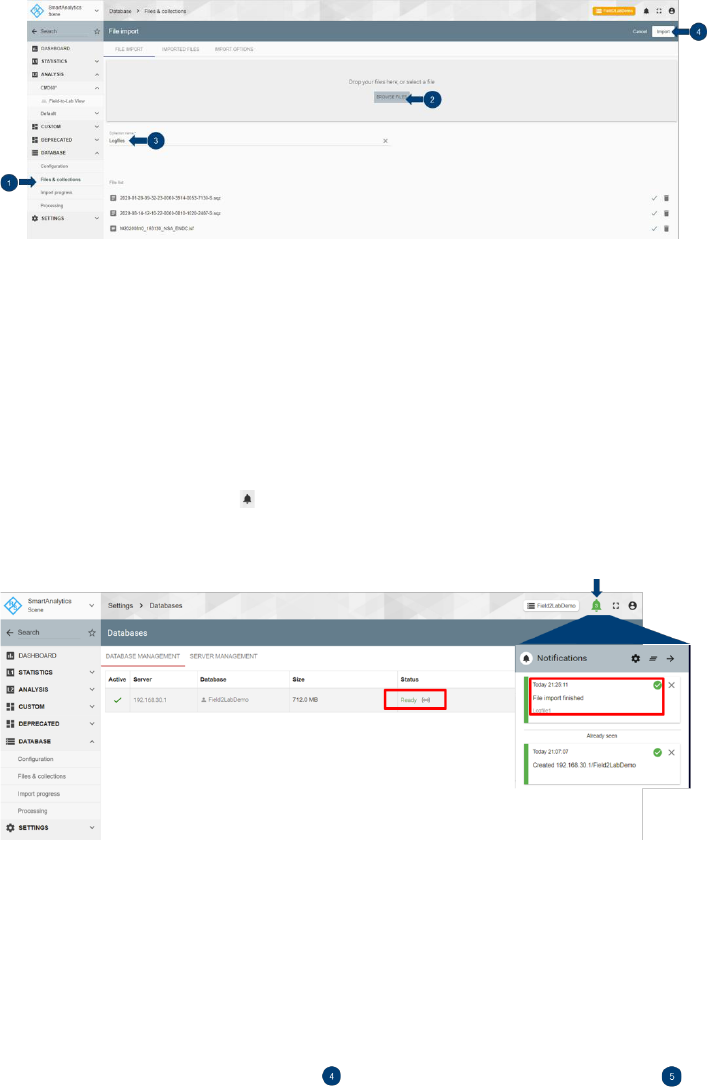
Fig. 2-6 Import the logfile in SmartAnalytics
1. Enter 'DATABASE' area and select 'Files & collections'
2. In the 'FILE IMPORT' tab, drag and drop the logfile directly in the window or use browser to navigate
and select. Import of multiple logfiles is allowed
3. Specify a name of the collection. One or multiple logfiles can be grouped in one collection.
4. Press 'Import' button and confirm the action with the 'OK' button in the popup dialog window
It might take a while to import the logfile. As long as the file is successfully imported into the active database,
open the notification panel at the upper right corner of the GUI, there should give the indication that the file
import is finished successfully. The status of current active database is turned to be 'Ready' as highlighted in
Fig. 2-7. From now on, the analyzing of the logfile can be started (see 2.2.3).
Fig. 2-7 Status of successful logfile import
Collection is similar to a folder in a file system. More file collections are allowed to be generated in the active
database in order to better organize the logfiles.
Further logfiles can be appended to the existing file collection with the same import procedure described
above. Of course, in order to allocate the logfile to the correct collection, the right name of the target file
collection should be identified beforehand and specified during the import procedure.
As shown in Fig. 2-8, the status of the collection(s) and the belonging files can be checked, and deleted if
desired (select the file to be deleted and press on 'DELETE FILE' button ).

Rohde & Schwarz | Application Note CM360° 14
Fig. 2-8 Check/Delete the imported files
2.2.3 Analyze Field Logfile
2.2.3.1 CM360° GUI Overview
2.2.3.1.1 Layout
CM360° GUI inherits the concept of native SmartAnalytics GUI design that is presented in Fig. 2-9.
Fig. 2-9 CM360° GUI
In general, the CM360° GUI is constructed by following parts:
► Scenario is the folders that consist of group of one or several workspaces. Per default, a scenario called
'CM360°' is created that comes from the initial CM360° installation.
► Workspace is the place to visualize the content of the database. The default workspace 'Field-to-Lab
View' is generated by the CM360° installation.
► Tab provides the different views of the data within one workspace. 'SUMMARY' and 'SIGNALING' tab
are populated in the provided 'Field-to-Lab view' workspace. Each tab consists of multiple panels.
'SUMMARY' tab gives more or less a high-level overview out of the logfile that is currently shown from
the file collection. It contains information, such as general information about the mobile network (network
operator name, country, MCC, MNC etc.), network information (cell ID, TAC etc.), data technology (LTE,
LTE-5GNR), UE capability, measured LTE and NR downlink power RSRP over the time. 'SIGNALING'

Rohde & Schwarz | Application Note CM360° 15
tab gives more insights of the imported logfile with respect to the Layer 3 protocol view, the decoded
message content of the selected L3 message, predefined or customized F2L KPI view etc.
► Session overview displays the session for a given point in time and its underlay radio access
technology (RAT). It supports the toggle of different UEs to visualize the sessions at a time. Per default,
session overview is hidden (see 2.2.3.1.2 for more details).
► Panel represents the window where the diverse information out of the imported logfile are displayed.
Various panels can be populated in SmartAnalytics, e.g. Field-to-Lab KPIs, UE capability panel etc.
Be noted that the workspace 'Field-to-Lab View' and scenario 'CM360°' are not editable. The modification of
the workspace is only allowed to be made on the copy of the original one.
2.2.3.1.2 Useful SmartAnalytics Features
Session Overview
Session overview in SmartAnalytics gives a good overview of the sessions in different perspectives, from
application, RAT etc. For sake of saving the display space, per default it is hidden. If desired, it can be
enabled as illustrated in Fig. 2-10.
Fig. 2-10 Toggle session overview
1. Click on the 'Toggle session overview' button in the controlling bar
2. Click on or to expand or collapse the detailed session overview, respectively.
3. Click on will allow to toggle the session overview between different UEs if more UEs are included in
the imported logfile.
Filter
The core of the SmartAnalytics is the database. The nature of a database allows the majority of the data
fields can be filtered. This simplifies the analysis and speeds up the problem drill-down. The filter can be set
by hovering the mouse over the field that contains an icon and clicking on that icon, e.g filtering on Layer 3
(L3) message, KPI Status, KPI Id etc. The applied filter(s) is(are) shown next to the workspace name in the
window title. The example in Fig. 2-11 shows 'RRCConnectionReconfiguration' message is chosen as a filter.

Rohde & Schwarz | Application Note CM360° 16
Fig. 2-11 Example of a filter function on 'RRCConnectionReconfiguration' message in SmartAnalytics
Synchronization
Time synchronization between diverse panels is achieved by hovering the mouse over and click on the that
is positioned next to the time stamp as shown in Fig. 2-12. This results in the time synchronization of the
views in different panels including the session overview.
Fig. 2-12 Time synchronization in SmartAnalytics
Shared link
Shared link allows the data analysis to be shared between different users. With this approach, different users
will have the same view of the analysis as the owner, e.g. the logfile under analyzing, the applied filter, time
position etc. In case the belonging database is a private one, the user needs to be assigned as the
ownership of the database in order to have the access to the shared link (see Fig. 2-5).

Rohde & Schwarz | Application Note CM360° 17
Fig. 2-13 Create a shared link
Snapshot Fig. 2-13 shows the way of creating the shared link. The created sharable link is automatically
copied in the clipboard. The link can then be pasted, e.g. through hot key combination Ctrl+V, and distributed
to the addressed party.
2.2.4 Script and Network Configuration Generation
In this section, script and network configuration generation are described which are based on the following
use cases
► In SmartAnalytics, identify the failed KPI from the field logfile, generate the Python test script comprising
the associated L3 message and the corresponding network configuration (see 2.2.4.1)
► In SmartAnalytics, extract the network configuration based on the imported field logfile and then apply it
to the device verification test cases later on in CMX (see 2.2.4.2)
2.2.4.1 Generate a Script Based on KPI
A typical use case of the CM360° solution is that the user identifies the failed KPI from the imported logfile in
the SmartAnalytics, analyzes the L3 message which is time aligned with the failed KPI and finally generates
a Python script. At the same time, the associated network configurations are also extracted from the logfile.
On CMX, the simulated test scenario based on the created Python script and network configurations can be
executed and verified by the Device Under Test (DUT) in question.
The steps described below shows the procedure how Python script and associated network configuration are
created.

Rohde & Schwarz | Application Note CM360° 18
Fig. 2-14 Create a script and network configuration
1. To reproduce the failure KPI in the lab, in 'Field-to-Lab KPIs' panel, filter out the KPI with 'Failed' status
and time synchronize with the corresponding L3 message in 'Protocol view' panel (see 2.2.3.1.2 for
more details about Filter and Time Synchronization function)
2. The associated L3 message is automatically highlighted in 'Protocol view' panel and select the message
by activating the check box
3. Click on the icon in the control bar to generate CMX compatible Python script
4. Confirm the script generation in the pop-up dialog box. In the text of the dialog box, important
information about XLAPI and CSW version of the CMX are shown which have to match the versions on
the CMX when the script is going to be executed later on (for more details, see 2.3).
5. After script is generated, enter the notification panel to check the notification. In successful case, the
generated Python script and its associated network configuration file .rsxp (file format with YAML
1
syntax) are available for download there.
Refer to Chapter 2.3 to learn more about the Python script execution.
2.2.4.2 Generate Network Configuration for Device Verification Test Case
As explained conceptually in Chapter 1.6, the focus of the use case described in this section is to extract the
network configurations from the imported logfile and then apply them to individual verification test case. With
this approach, DUT can then be tested against a particular test case under different network configuration
condition.
The network configuration file is created also based on the selected messages in the 'Protocol view' panel.
The selectable messages are MIB, SIB or L3 RRCConnectionReconfiguration message. They can be chosen
1
YAML stands for 'Yet Another Markup Language'. Like JavaScript Object Notation (JSON), it is a human readable markup language commonly
used for configuration files.

Rohde & Schwarz | Application Note CM360° 19
with the help of the filter function (see 2.2.3.1.2). The whole procedure is similar to the use case described in
section 2.2.4.1.
As shown in Fig. 2-15, three steps are needed to create network configuration file
Fig. 2-15 Create network configuration file
1. In 'Protocol View' panel, filter out the cell that is in question based on the Physical Cell ID (PCI) using
filter icon next to the PCI, e.g. PCI = 409. The applied filter is then shown next to the workspace name
on the top.
2. Select one of the filtered messages, MIB, SIB or RRCConnectionReconfiguration message
3. Same as described in 2.2.4.1, click on the icon in the control bar to generate network config file (the
generated Python script is superfluous in this application here).
The created network configuration file (.rsxp) can be downloaded and applied to the device verification test
case at the test case execution. Refer to chapter 2.3 for more details about the adoption of the network
configuration when executing a Python script.
2.2.4.3 Structure of the Script and Network Configuration
2.2.4.3.1 Python Script
The generated Python test script (.py) has fixed structure. Basically, it consists of three parts, i.e. meta data,
preamble and test body.
Meta data contains information about
► XLAPI version (make sure that the installed XLAPI version on CMX matches the one given here)
► SmartAnalytics shared link used to create the script
► UE, network operator and logfile information (name and start time stamp of the logfile)
► Summary
─ Describes the general rules of the script generation
─ The user selected messages in the protocol view of the SmartAnalytics

Rohde & Schwarz | Application Note CM360° 20
─ Detected procedures
─ Cells summary
─ More information about the script creation
Preamble creates and configures the LTE and NR cells according to the information based on the user
selected messages.
Test body takes care of the procedures, such as UE attaches to the LTE cell, establishes the EPS dedicated
bearer (NR SCG Bearer) and activates the NSA SCG Bearer etc.
2.2.4.3.2 Network Configuration
The associated network configuration file (.rsxp) has the structure as follows as an example:
#YAML data
#Detected cells configuration in YAML format.
#Please change the cell names as per script terminology.
#This configuration can be used as test parameters data in XLAPI and
CMsequencer.
#Configure LTE cell
- LteCell:
name: LTE Cell 0
config:
- phy_cell_id: 359
- total_dl_power: -50
- earfcn: 1850
- num_crs_antenna_ports: 2
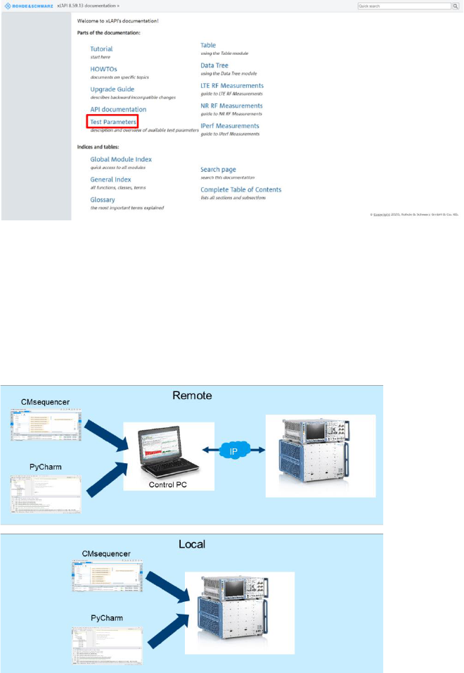
The test parameters of network configuration file that are supported by XLAPI can be referred to XLAPI
online help document from the XLAPI installation which is accessible from the following link
C:\Users\Public\Documents\Rohde-Schwarz\XLAPI\<XLAPI version>
2
\XLAPI Help
On the home page of the XLAPI online help document, enter 'Test Parameters' area to get more detailed
information about the parameters (see Fig. 2-16) or refer to section 5.3.2 of [6] alternatively.
2
This is a placeholder. The installed XLAPI version under which the script is going to be executed should be filled here.
Rohde & Schwarz | Application Note CM360° 21
Fig. 2-16 Reference of test parameters in XLAPI help
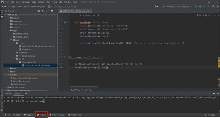
2.3 Test Script Execution
The Python test script can be run directly in PyCharm integrated development environment (IDE) (see 2.3.2)
or converted into a building block and executed in CMsequencer (see 2.3.3). The execution can be initiated
either locally on CMX or remotely from a control PC as illustrated in Fig. 2-17.
Fig. 2-17 Run Python script (remotely or locally) in PyCharm or in CMsequencer
2.3.1 General
Prerequisites of test script execution
► CMX with either minimum footprint or extended setup that determines the number of supported cells [9]
► Composite software is installed on CMX, refer to [9]
► As part of the CMX composite software, XLAPI software (Python virtual environment and XLAPI
firmware) are installed via R&S Installation Manager (IM) on the CMX and optionally also on control PC
if remote script execution is desired, refer to [6]. The same XLAPI version should be installed as the one
indicated in the script generation in SmartAnalytics (see 2.2.4.1)

Rohde & Schwarz | Application Note CM360° 22
► Python IDE needs to be installed on CMX locally and optionally also on control PC if remote script
execution is desired. A recommended IDE is PyCharm Community Edition (downloadable at:
https://www.jetbrains.com/de-de/pycharm/download/#section=windows)
► Place the generated Python script to following folder on control PC (for remote execution) or on CMX
(for local execution)
C:\Users\Public\Documents\Rohde-Schwarz\XLAPI\<XLAPI version>\appl\ng-
f2l\generated_script
► Place the network configuration file to following folder on control PC (for remote execution) or on CMX
(for local execution)
C:\Users\Public\Documents\Rohde-Schwarz\XLAPI\<XLAPI
version>\appl\user\config
IP setting on control PC to enable the remote Python script execution
In order to enable the remote execution of the Python script from the control PC, ensure the IP connectivity
between the control PC and CMX at first.
Then, on the control PC, the IP address or the hostname of the CMX needs to be specified either globally for
all the scripts or for specific script as described in the following text. As an example, CMX IP address
'192.168.0.1' is in use here.
Set the global IP address
Open a Python console in PyCharm, and enter (see Fig. 2-18):
from xlapi import settings
settings.system.set_instrument_address("192.168.0.1")
Check the global IP address
To check the global IP address that has been set, issue the command in the Python console (see Fig. 2-18)
settings.system.get_instrument_address()
This should return the configured IP address.
Fig. 2-18 Set and check the global IP address
By setting the global IP address or hostname in this way, the setting persists not only during the current
Python session but also in following sessions unless the setting is overwritten or XLAPI is uninstalled.
Set IP address for specific script
Each test script generated by SmartAnalytics contains a line of code to specify the instrument address which
is per default commented out. To allow the test script to be run remotely from a control PC, this code line
needs to be uncommented and the IP address or hostname of CMX has to be entered there, e.g. CMX IP
address 192.168.0.1 (see Fig. 2-19)
settings.system.set_instrument_address("192.168.0.1")
Fig. 2-19 Specify the IP address of instrument in Python script for remote execution
Rohde & Schwarz | Application Note CM360° 23
It is a runtime setting. Therefore, it is only bounded locally to the affected Python script.
2.3.2 Run Python Script in PyCharm
The operations described in this section is valid both for remote and local script execution on control PC and
on CMX, respectively.
Two major ways to run the script in PyCharm are introduced, either in the PyCharm Terminal (on the
command line) or directly from the PyCharm project list. See [6] for more details.
Run the script in PyCharm Terminal
1. Open Python Terminal
─ either in PyCharm (see Fig. 2-20)
─ or run C:\Users\Public\Documents\Rohde-Schwarz\XLAPI\<XLAPI
version>LaunchTerminal.bat
Fig. 2-20 Launch Python terminal in PyCharm
2. In the Python Terminal, issue command:
py <python script name> --test-param-files <network configuration file>
e.g.
py appl\user\ng-f2l\generated_script\2021_05_03_14_24_55_script.py --test-
param-files appl\user\config\2021_05_03_14_24_55_nw_params.rsxp
Run directly from PyCharm project list
1. Specify the network configuration file (Fig. 2-21)
Right mouse click on the test script in the project list, in the drop down menu, select 'Modify Run
Configuration', enter following string in the 'Parameters' field: --test-param-files <network
configuration file>,
e.g. --test-param-files appl\user\config\2021_05_03_14_24_55_nw_params.rsxp


Rohde & Schwarz | Application Note CM360° 25
2.3.3 Run Script in CMsequencer
As an alternative to run Python script in PyCharm described in 2.3.2, the script can also be executed in
CMsequencer as a building block. See [7] for more details about the handling in CMsequencer.
The CMsequencer building block is always generated and stored on CMX which can later on be loaded and
executed remotely or locally in the Web based CMsquares in a Web browser.
Generate CMsequencer building block out of Python script on CMX.
1. First of all, an external tool (SendToSequencer.exe) has to be specified in PyCharm [6]. This is an
one-time assignment in PyCharm (see Fig. 2-23).
Fig. 2-23 Add external tool 'Send to CMsequencer' in PyCharm
a) In PyCharm on CMX, select 'File > Settings' from the top menu.
b) From the 'Settings' menu, select 'Tools > External Tools'.
c) Click the '+' icon to open the 'Create Tool' dialog for adding an external tool.
d) Configure the tool by setting the values in the 'Create Tool' input fields:
─ 'Name': Enter the name of the tool that is shown in PyCharm, for example, Send to
CMsequencer.
─ 'Description': Optionally, enter a short description of the tool, for example Creates a building
block for the CMsequencer.
─ 'Program': Enter the path to the tool's execution file, C:\Program Files\Rohde-
Schwarz\CMsequencer\Send to CMsequencer Wizard\SendToSequencer.exe.
─ 'Arguments': Enter the path to the tool's script file, $FilePath$.
─ 'Working Directory': Enter an appropriate working directory for the tool, for example
$ContentRoot$.
e) Click 'OK' to finish the configuration. Click 'OK' again to close the settings.
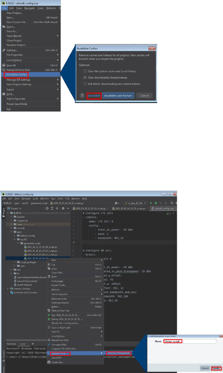
f) Restart PyCharm in the following way (Fig. 2-24):
─ Select 'File > Invalidate Caches / Restart' from the top menu.
─ At the 'Invalidate Caches' dialog, click the 'Just Restart' button.
Rohde & Schwarz | Application Note CM360° 26
Fig. 2-24 Restart PyCharm
2. Generate CMsequencer building block in PyCharm (see Fig. 2-25)
a) Right mouse click on the Python test script, in the drop down menu, select 'External Tools' option
b) Select 'Send to CMsequencer' to run the external tool
c) In the launched XLAPI building block creation wizard, enter the name of the building block, e.g.
Demo_script. After pressing on 'Create', the corresponding CMsequencer building block of the
selected Python test script is then automatically created
Fig. 2-25 Run external tool 'Send to CMsequencer' in PyCharm
3. Load the building block in CMsequencer (see Fig. 2-26)

Rohde & Schwarz | Application Note CM360° 27
Fig. 2-26 Load CMsequencer block
a) Enter CMsquares either locally on CMX (enter localhost:5555 in the Web browser on CMX) or
remotely from the control PC (enter <IP address or hostname of CMX>:5555 in the Web
browser on control PC). Select 'Sequencer' from the CMsquares's main window
b) In 'Sequence Editor', under 'User Items > Test Scripts > Uploads', the generated building block is
shown, e.g. Demo_script created in step 2 on page 26
c) Choose the building block
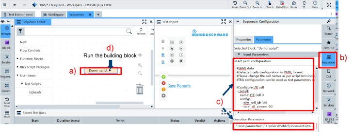
4. Run the building block (see Fig. 2-27)
a) Click on the building block name to enter its configuration mode
b) Select 'Sequencer' function block on the right side of the GUI, it opens the sequencer configuration
where the network configuration can be entered.
c) One of two possible ways can be adopted to assign the network configuration to the building block,
either paste the YAML file content (.rsxp) in plain text in 'Input Parameters' window or enter string
"--test-param-files","C:\Users\Public\Documents\Rohde-
Schwarz\XLAPI\<XLAPI
version>\appl\user\config\2021_05_03_14_24_55_nw_params.rsxp" in 'execution
parameters' field to specify the network configuration file
d) Finally, click on the play button next to the building block name to run
Rohde & Schwarz | Application Note CM360° 28
Fig. 2-27 Configure the network configuration and run the building block
2.3.4 Run Device Verification Test Case
In principle the same concept described in section 2.3.1, 2.3.2 and 2.3.3 should be applied, but instead of
using the Python test script generated by SmartAnalytics, off-the-shelf device verification test cases are used
here.
The device verification test case package needs to be installed on CMX beforehand via an installer that
belongs to the CM360° software distribution. After the installation, the test cases are available on CMX as
Python scripts or listed as building blocks in CMsequencer.
The test case scripts are stored under: C:\Users\Public\Documents\Rohde-
Schwarz\XLAPI\<XLAPI version>\appl\script_packages\cmx_f2l_device_verification
The building blocks of device verification test cases can be found in 'Sequence Editor' under menu item
'R&S Script Packages > CMX_F2L_DEVICE_VERIFICATION > <XLAPI version>'
If device verification test cases are about to be executed in PyCharm environment, refer to 2.3.2 to see how
the network configuration file is applied to the Python script.
In case the device verification test cases are run as building blocks in CMsequencer, refer step 4 of chapter
2.3.3 (on page 27) to see the usage of the network configuration file in CMsequencer.
A work flow of running a device verification test case in CMsequencer by applying the network configuration
generated in the SmartAnalytics (see 2.2.4.2 for details about the network configuration generation) is
illustrated in Fig. 2-28.

Rohde & Schwarz | Application Note CM360° 29
Fig. 2-28 Run device verification test case in CMsequencer by applying network configuration file created in SmartAnalytics
3 Outlook
The procedures and features described in this document reflect the status quo implementation. CM360°
solution strives to offer more capabilities to meet the dynamic market demands. There are planned upcoming
features, such as
► 5G Standalone (SA)
► IMS VoLTE & VoNR
► Generate CMsequencer test scripts & Network profiles
► Connected mobility (handover)
4 Literature
[1]
GSA, "5G Market: Snapshot April 2021".
[2]
R&S SwissQual AG, "R&S SwissQual AG® SmartAnalytics Scene Installation Manual".
[3]
R&S SwissQual AG, "R&S SwissQual AG® KPI Users Guide Manual Release 20.2".
[4]
R&S SwissQual AG, "R&S SwissQual AG® SmartAnalytics Scene Manual Release 21.0".
[5]
R&S, "R&S®CMX500 Radio Communication Tester User Manual".
[6]
R&S, "R&S®CMX500 XLAPI Scripting Interface User Manual".

Rohde & Schwarz | Application Note CM360° 30
[7]
R&S, "R&S®CMsequencer User Manual".
[8]
R&S, "Drive Test Software R&S®ROMES4 Operating Manual".
[9]
R&S, "R&S®CMX500/CMW500 5G NR FR1 Test Setup Quick Setup Instructions".
5 Ordering Information
Designation
Type
Order No.
CM360degrees F2L for 5G Sales bundle
R&S
®
CM360-F2L
1900.6478.17

Rohde & Schwarz
The Rohde & Schwarz electronics group offers
innovative solutions in the following business fields: test
and measurement, broadcast and media, secure
communications, cybersecurity, monitoring and network
testing. Founded more than 80 years ago, the
independent company which is headquartered in
Munich, Germany, has an extensive sales and service
network with locations in more than 70 countries.
www.rohde-schwarz.com
Rohde & Schwarz training
www.training.rohde-schwarz.com
Rohde & Schwarz customer support
www.rohde-schwarz.com/support
Certified Quality Management
ISO 9001
PAD-T-M: 3572.7186.00
/01.00/EN
R&S
®
is a registered trademark of Rohde & Schwarz GmbH & Co. KG
Trade names are trademarks of the owners.
1SL369 | Version 0e | 06.2021
Application Note | CM360°
Data without tolerance limits is not binding | Subject to change
© 2021 Rohde & Schwarz GmbH & Co. KG | 81671 Munich, Germany
www.rohde-schwarz.com
