
Deploying Scalable Time
Distribution within a
Converged Plantwide
Ethernet Architecture
Design Guide
May 2019
Document Reference Number: ENET-TD016A-EN-P

iii
Deploying Scalable Time Distribution within a Converged Plantwide Ethernet Architecture
ENET-TD016A-EN-P
Preface
Converged Plantwide Ethernet (CPwE) is a collection of tested and validated architectures. The testing and
validation follow the Cisco Validated Design (CVD) and Cisco Reference Design (CRD) methodologies. The
content of CPwE, which is relevant to both operational technology (OT) and informational technology (IT)
disciplines, consists of documented architectures, best practices, guidance, and configuration settings to help
industrial operations and OEMs achieve the design and deployment of a scalable, reliable, secure, and
future-ready plant-wide industrial network infrastructure. CPwE can also help industrial operations and
OEMs achieve cost reduction benefits using proven designs that can facilitate quicker deployment while
helping to minimize risk in deploying new technology. CPwE is brought to market through an ecosystem
consisting of Cisco, Panduit, and Rockwell Automation emergent from the strategic alliance between Cisco
Systems and Rockwell Automation.
Deploying Scalable Time Distribution within a Converged Plantwide Ethernet Architecture CRD (CPwE
Time), which is documented in this Design Guide (DG), outlines several use cases for designing and
deploying Scalable Time Distribution technology throughout a plant-wide Industrial Automation and Control
System (IACS) network infrastructure. CPwE Time highlights the key IACS application requirements,
technology, and supporting design considerations to help with the successful design and deployment of these
specific use cases within the CPwE framework. CPwE Time was architected, tested, and verified by Cisco
Systems and Rockwell Automation with assistance by Panduit.
Document Organization
This document is composed of the following chapters and appendices.
Chapter/Appendix Description
CPwE Scalable Time
Distribution Overview
Overview of CPwE Time.
CPwE Scalable Time
Distribution Design
Considerations
Describes primary design considerations when choosing how to implement
CPwE Time in an IACS architecture.
CPwE Scalable Time
Distribution
Configuration
Describes how to configure CPwE Time within the CPwE architecture based
on the design considerations and recommendations of the previous chapter.

iv
Deploying Scalable Time Distribution within a Converged Plantwide Ethernet Architecture
ENET-TD016A-EN-P
Preface
For More Information
More information on CPwE Design and Implementation Guides can be found at the following URLs:
• Rockwell Automation site:
– http://www.rockwellautomation.com/global/products-technologies/network-technology/architectures
.page?
• Cisco site:
– http://www.cisco.com/c/en/us/solutions/enterprise/design-zone-manufacturing/landing_ettf.html
Note This release of the CPwE architecture focuses on EtherNet/IP
™
, which uses the ODVA, Inc. Common
Industrial Protocol (CIP
™
), and is ready for the Industrial Internet of Things (IIoT). For more information on
EtherNet/IP and CIP Sync
™
, see odva.org at the following URL:
• http://www.odva.org/Technology-Standards/EtherNet-IP/Overview
Test Hardware and
Software
Lists the Cisco and Rockwell Automation hardware and software used in
testing the CPwE Time solution.
References Links to documents and websites that are relevant to Deploying Scalable Time
Distribution within a Converged Plantwide Ethernet Architecture Design
Guide.
Acronyms List of all acronyms and initialisms used in this document.
About the Cisco Validated
Design (CVD) Program
Describes the Cisco Validated Design (CVD) process and the distinction
between CVDs and Cisco Reference Designs (CRDs).
Chapter/Appendix Description

CHAPTER
1-1
Deploying Scalable Time Distribution within a Converged Plantwide Ethernet Architecture
ENET-TD016A-EN-P
1
CPwE Scalable Time Distribution Overview
The prevailing trend in Industrial Automation and Control System (IACS) networking is the convergence of
technology, specifically IACS operational technology (OT) with information technology (IT). Converged
Plantwide Ethernet (CPwE) helps to enable IACS network and security technology and OT-IT persona
convergence through the use of standard Ethernet, Internet Protocol (IP), network services, security services,
time synchronization technologies, and EtherNet/IP. A real-time converged plant-wide IACS architecture
helps to enable the Industrial Internet of Things (IIoT).
Business practices, corporate standards, policies, industry standards, and tolerance to risk are key factors in
determining the degree of time synchronization required within a plant-wide IACS architecture. IACS
networks differ from their IT counterparts in their need to support significantly lower latency (time delay
between message sent and message received) and jitter (the variance of the latency) to help enable real-time
IACS communications. Time synchronization helps to support time-critical data for the most demanding
IACS applications.
Successful deployment of IIoT IACS applications within CPwE Architectures (Figure 1-1) depends on a
network infrastructure design that addresses IACS application performance requirements. The content of
CPwE, which is relevant to both OT and IT disciplines, consists of documented architectures and key tenets
from OT and IT to help achieve real-time communications to support IIoT IACS applications. CPwE key
tenets include:
• Smart IIoT Devices—controllers, I/O, drives, instrumentation, actuators and analytics
• Zoning (segmentation)—smaller connected LANs, functional areas and security groups
• Managed Infrastructure—managed industrial Ethernet switches (IES) and industrial firewalls
• Resiliency—robust physical layer and resilient or redundant topologies with resiliency protocols
• Time-critical Data—data prioritization and time synchronization via CIP Sync and IEEE-1588
Precision Time Protocol (PTP)
• Wireless—unified wireless LAN (WLAN) to enable mobility for personnel and equipment
• Holistic Defense-in-Depth Security—multiple layers of diverse technologies for threat detection and
prevention, implemented by different persona (e.g., OT and IT) and applied at different levels of the
plant-wide IACS architecture
• Convergence-ready—seamless plant-wide integration by trusted partner applications

1-2
Deploying Scalable Time Distribution within a Converged Plantwide Ethernet Architecture
ENET-TD016A-EN-P
Chapter 1 CPwE Scalable Time Distribution Overview
CPwE Time Solution Use Cases
The ODVA, Inc. CIP Sync technology uses the Common Industrial Protocol (CIP) application layer protocol
and the IEEE 1588-2008 Precision Time Protocol (PTP) standard for time synchronization. CIP Sync and
IEEE 1588-2008 are designed for local and plant-wide IACS applications requiring very high accuracies
beyond those attainable with Network Time Protocol (NTP).
This Deploying Scalable Time Distribution within a Converged Plantwide Ethernet Architecture Design
Guide (CPwE Time) outlines several use cases for designing and deploying IEEE 1588 PTP and CIP Sync
technology throughout a plant-wide IACS network infrastructure. CPwE Time was architected, tested and
verified by Cisco Systems and Rockwell Automation with assistance by Panduit.
CPwE Time Solution Use Cases
CPwE is the underlying architecture that provides standard network and security services for control and
information disciplines, devices and equipment found in modern IACS applications. The CPwE architectures
(Figure 1-1) were architected, tested and validated to provide design and implementation guidance, test
results and documented configuration settings. This can help to achieve the real-time communication,
reliability, scalability, security and resiliency requirements of modern IACS applications.
An IACS is deployed in a wide variety of discrete and process manufacturing industries such as automotive,
pharmaceuticals, consumer packaged goods, pulp and paper, oil and gas, water/wastewater, mining and
energy. IACS applications are composed of multiple control and information disciplines such as continuous
process, batch and discrete, and hybrid combinations. One of the challenges facing industrial operations is the
hardening of standard Ethernet and IP-converged IACS networking technologies to take advantage of the
business benefits associated with IIoT.
This Deploying Scalable Time Distribution within a Converged Plantwide Ethernet Architecture Design
Guide outlines the concepts, requirements and technology solutions for reference designs developed around
a specific set of priority use cases. These use cases were architected and tested for solution functional
verification with limited scale by Cisco Systems and Rockwell Automation with assistance by Panduit to help
support time synchronization within a converged plant-wide EtherNet/IP IACS architecture.
The CPwE Time Design Guide includes:
• Time Synchronization Overview:
–
IEEE 1588 Precision Time Protocol (PTP)
–
ODVA, Inc. CIP Sync
• Time Synchronization Use Cases—the following represents a portion of the use cases:
–
Time stamping
–
First fault detection
–
Sequence of Events (SOE)
–
Distributed motion (not included in CPwE Time)
• Plant-wide Architectures for Reliable Time Synchronization:
–
Design, configuration and diagnostic considerations for plant-wide (Levels 0-3) IEEE 1588 PTP and
CIP Sync deployments
–
Limited resiliency and reliability PoC testing
• Selection of Industrial Ethernet Switches (IES):
–
Layer 2 IES—Allen-Bradley
®
Stratix
®
5700/5400
–
Layer 3 IES—Allen-Bradley Stratix 5410

1-3
Deploying Scalable Time Distribution within a Converged Plantwide Ethernet Architecture
ENET-TD016A-EN-P
Chapter 1 CPwE Scalable Time Distribution Overview
CPwE Time Architecture Overview
Figure 1-1 CPwE Architectures
CPwE Time Architecture Overview
ODVA, Inc. CIP Sync technology for time synchronization is used across a broad range of IACS applications
to synchronize control system clocks (Figure 1-2) and helps enable applications such as event sequencing and
logging. For example:
• A sequence of events or first fault system can use timestamps to determine the order in which faults
occurred in the system. This allows for the tracking of faults to establish the first in a chain of faults.
These types of applications use dedicated alarm instructions in the Programmable Automation Controller
(PAC) to record events or time stamping inputs in order to log the change of state for a point.
• An in-PAC chassis historian module logs historical data at Level 1 (skid/machine).
• High-speed applications can use timestamps to process inputs and outputs asynchronously from the
control loop. For example, an application can use time-synchronized inputs and outputs to trigger a
diverter without the application scan time matching the part cycle time.
CIP Sync uses IEEE 1588 Precision Time Protocol (PTP) to synchronize clocks in the control system. In the
PTP architecture, all clocks are synchronized to a single grandmaster clock. In turn, this clock must be
synchronized to Coordinated Universal Time (UTC) to represent the time of day in the system.
Several approaches exist for setting time in the grandmaster clock that allow customers to meet different
application requirements. For example, applications that only require rough correlation to UTC can use a
handset grandmaster clock. In this case, the administrator simply sets the time in the grandmaster clock based

1-4
Deploying Scalable Time Distribution within a Converged Plantwide Ethernet Architecture
ENET-TD016A-EN-P
Chapter 1 CPwE Scalable Time Distribution Overview
CPwE Time Architecture Overview
on the time that is currently shown on another device such as their PC or smartphone. All clocks drift over
time and need to be adjusted to accurately reflect UTC. Handset clocks do not have any inherent mechanism
to compensate for drift. As such, the administrator will need to re-adjust the grandmaster time manually to
ensure alignment with UTC time. This readjustment will need to be done on a regular basis to help prevent
the two clocks from drifting too far apart.
Applications that require tight correlation to UTC can use a grandmaster clock with a built-in Global
Navigation Satellite System (GNSS) receiver such as a Layer 3 IES or a dedicated PAC module (e.g.,
Allen-Bradley 1756-TIME module). These type of grandmaster clocks synchronize to the atomic clocks in
the navigation satellites and automatically adjust their time to match UTC. However, the installation of these
systems is complex and requires an antenna with an unobstructed view of the sky and low loss coaxial cable
to connect to the receiver.
A final approach is the NTP-PTP flywheel feature available in some IES. This is a hybrid approach that uses
Network Time Protocol (NTP) to synchronize and regulate the grandmaster clock to UTC. Correlation to
UTC will not be as good as with a GNSS receiver; however, the flywheel does compensate for drift.

1-5
Deploying Scalable Time Distribution within a Converged Plantwide Ethernet Architecture
ENET-TD016A-EN-P
Chapter 1 CPwE Scalable Time Distribution Overview
CPwE Time Architecture Overview
Figure 1-2 CPwE Time Architecture
In the CPwE Time solution (Figure 1-2), PTP time does not pass through the core and the PTP domain is
bounded to the Cell/Area Zones connected to a single Layer 3 IES distribution pair. Within these bounds, the
grandmaster clock will function as the reference for all PTP IACS devices in the plant-wide architecture. The
preferred solution for the network topology is redundant star, however ring may work for some use cases. In
either case, synchronization should be sufficient to support time stamping functionality of I/O modules that
typically have a resolution of ±4µs to ±100µs. However, the accuracy of the timestamps to UTC will be
limited by how well the grandmaster clock is correlated to UTC. Since PTP time does not synchronize across
the core, correlation between PTP domains is also limited by how well the grandmaster in each of the PTP
domains is correlated to UTC.
For more information on CIP Sync and CIP Sync applications, see Integrated Architecture and CIP Sync
Configuration
https://literature.rockwellautomation.com/idc/groups/literature/documents/at/ia-at003_-en-p.pdf
Industrial Zone
Levels 0-3
(Plant-wide Network)
Enterprise WAN
Industrial Demilitarized
Zone (IDMZ)
Level 3
Site Operations
(Control Room)
Cell/Area Zone - Levels 0-2
Redundant Star Topology - MSTP Resiliency
Active
Layer 3 IES
HSRP Resiliency
Standby
Layer 3 IES
HSRP Resiliency
Catalyst 4500-X
VSS Resiliency
Ce
ll
/A
re
a
Zo
ne
-
Le
ve
ls
0
-
2
Redundant Star Topolo
gy
-
MSTP Resilienc
y
Ac
t
i
v
e
L
a
ye
r 3 IE
S
HS
RP Resilienc
y
S
tandb
y
L
a
ye
r
3
IE
S
HS
RP Resilienc
y
Controller ControllerTime Stamping I/O Time Stamping I/O Time Stamping I/O
MSTP
Cell/Area Zone - Levels 0-2
Redundant Star Topology - MSTP Resiliency
GPS
Reference
Clock
IES
IES
IES
379460
Time Synchronized to UTC
Single PTP Domain

CHAPTER
2-1
Deploying Scalable Time Distribution within a Converged Plantwide Ethernet Architecture
ENET-TD016A-EN-P
2
CPwE Scalable Time Distribution Design
Considerations
Reference Clocks
Reference clocks are the master time source for a plant-wide Industrial Automation and Control System
(IACS) architecture. They are high precision clocks that are synchronized to a time standard such as
International Atomic Time (TAI) or Coordinated Universal Time (UTC). TAI uses a system of hundreds of
atomic clocks to accurately track time using International System of Units (SI) seconds. The SI second is a
fixed measurement and is not compensated for changes in the notional period of the Earth.
UTC is the time scale people use to track time of day. UTC is based on TAI time and the SI second, however
it uses leap seconds to align clocks with solar time. Periodically, leap seconds are added to adjust UTC time
to the solar day. As of December 2015, UTC is 37 seconds behind TAI. All clocks in the system should
synchronize directly or indirectly with the reference clock to provide a consistent view of time across the
IACS application network infrastructure.
Global Navigation Satellite Systems
Global Navigation Satellite Systems (GNSS) such as the Global Positioning System (GPS) can be used to
provide accurate reference time for network systems, for instance, time-critical IACS applications. GNSS
navigation systems function by measuring the time delay between a receiver and one or more satellites. For
these navigation systems to function, they must have highly accurate atomic clocks in each satellite. GNSS
timeservers use these signals to synchronize their internal clock to the atomic clocks in the satellites. This
allows the GNSS timeserver to provide very accurate synchronization to UTC. GNSS-based solutions also
automatically handle leap seconds. Most GNSS receivers can output time as an NTP server. Some timeservers
such as the 1756-TIME, Allen-Bradley Stratix 5410, and Cisco IE 5000 industrial Ethernet switches (IES)
can function as a PTP grandmaster clock.

2-2
Deploying Scalable Time Distribution within a Converged Plantwide Ethernet Architecture
ENET-TD016A-EN-P
Chapter 2 CPwE Scalable Time Distribution Design Considerations
Reference Clocks
Network Time Protocol
Network Time Protocol (NTP) servers are commonly used to provide a reference clock for enterprise and
IACS applications. NTP-based systems have an advantage because they do not require complicated satellite
receivers to provide reference time for the system. However, the fact that the IACS application is
synchronizing to a reference clock across a network limits the accuracy of the solution. NTP-based solutions
will maintain an approximate synchronization to UTC and handle events like leap seconds.
Internal Clock
Internal clocks are free running oscillators inside IACS devices like Programmable Automation Controllers
(PACs). Internal clocks need to be manually set to UTC by an administrator, such as an authorized OT
engineer (e.g., Control Systems Engineer). Furthermore, all clocks drift over time and internal clocks do not
have an automated mechanism for correcting drift. If clock accuracy to UTC becomes unacceptable due to
drift or leap seconds, the administrator must manually correct the time in the clock.
Reference Clock Location
The location of the reference clock can have an impact on how well IACS devices in the IACS application
synchronize to each other and to UTC. The ability of IES and IACS devices to synchronize across the network
is generally impacted by factors such as bandwidth, latency, and jitter. These are some of the driving factors
for the location of the reference clock. Availability is another consideration which may influence the
placement of the reference clock. The reference clock should be positioned within the plant-wide IACS
architecture so that the time synchronization architecture can meet the application requirements.
Internet
Protocols like NTP allow systems to synchronize to reference clocks located anywhere in the world. These
reference clocks are hosted by a number of different types of organizations and the quality of the time service
may vary widely:
• Government entities
• Corporations
• Educational institutions
Generally, reference clock sources offered by these organizations are reliable based on the limits of the NTP
protocol. However, there are risks associated with using internet-based reference clocks. Most of these
services are provided on a volunteer basis and could be changed or discontinued at any time. Furthermore,
many public NTP servers do not provide any security to authenticate or verify the integrity of the time
sources. Because of this, IT administrators should consider if the use of internet-based reference clocks is
appropriate for their application needs. In addition, accessing internet-based NTP servers from the Industrial
Zone is problematic since the traffic must flow through both the Industrial Demilitarized Zone (IDMZ) and
the enterprise edge firewalls.
Enterprise Zone
Placing the reference clock in the Enterprise Zone places it directly under the authority of the IT organization.
IT departments commonly deploy reference clocks to reliably synchronize their computer and network
systems to a common time using NTP. Like internet-based NTP servers, these internal servers could be used

2-3
Deploying Scalable Time Distribution within a Converged Plantwide Ethernet Architecture
ENET-TD016A-EN-P
Chapter 2 CPwE Scalable Time Distribution Design Considerations
Network Time Protocol
as the time reference for IACS applications. However, as with internet-based sources it is important to
consider the path between the IACS network and the enterprise time servers. If the Industrial Zone is
connected to the headquarters site using a low bandwidth, high latency, and high jitter wide area network
(WAN) link the accuracy and stability of time could be impacted. Furthermore, these deployments generally
will not support applications where the reference clock must feed PTP time directly into the IACS application.
The Securely Traversing IACS Data across the Industrial Demilitarized Zone Design and Implementation
Guide discusses passing NTP through the IDMZ.
https://literature.rockwellautomation.com/idc/groups/literature/documents/td/enet-td009_-en-p.pdf
Industrial Zone
From an IACS application perspective, placing the reference clocks directly in the Industrial Zone should
provide the best quality of time synchronization and accuracy to UTC. This approach also allows the
reference clock to source PTP time directly into the IACS application without converting NTP to PTP. The
tradeoff is that a reference clock such as a GNSS receiver must be installed in the Industrial Zone.
Network Time Protocol
Network Time Protocol (NTP) is the Internet Engineering Task Force (IETF) standard for synchronizing
clocks across the Internet and TCP/IP networks in general. NTP uses a hierarchical system of clocks to
synchronize time across disparate hosts on the network. There are three roles for clocks in the NTP
architecture:
• Servers—NTP servers act as a time source for one or more NTP clients.
• Clients—NTP clients synchronize their clocks to one or more servers.
• Peers—NTP peers allow two clocks to synchronize to each other. In essence, peers are clients and servers
to each other.
These roles are not exclusive and any clock in the plant-wide IACS architecture can act as one or more of
these roles. For example, an NTP server is generally a client to servers higher up in the NTP hierarchy.
NTP has limited provisions for authenticating timeservers. Most implementations support symmetric keys for
authentication. Some recent implementations support the autokey security protocol. NTP authentication is
outside the scope for this guide.
Some clients implement the Simple Network Time Protocol (SNTP). SNTP is a simplified version of the NTP
daemon (computer program that runs as a background process) and generally has lower precision than the full
NTP protocol.
NTP Hierarchy
The clock hierarchy (Figure 2-1) is divided into “stratum” where lower stratum numbers are closer to the
reference clock. The reference clock is identified as the stratum 0 clock and is frequently a receiver for a
GNSS such as a GPS, but could also be a radio receiver, atomic clock, or another precision time source. The
stratum 0 clock is directly connected to the stratum 1 server and cannot be directly accessed across the
network. The stratum 2 servers are the first to synchronize across the network using the NTP protocol. They
are clients to several stratum 1 servers and are frequently peers to other stratum 2 servers. The stratum 3
servers are clients to the stratum 2 servers and may be peers to other stratum 3 servers and so on.

2-4
Deploying Scalable Time Distribution within a Converged Plantwide Ethernet Architecture
ENET-TD016A-EN-P
Chapter 2 CPwE Scalable Time Distribution Design Considerations
Network Time Protocol
Figure 2-1 NTP Hierarchy
Generally, the ability of a client (e.g., IACS device) to synchronize its clock to the reference depends on its
stratum level. Clocks with lower stratum numbers will be more tightly synchronized with the reference clock.
NTP clocks will have limited accuracy to UTC. They are generally a better fit for IACS applications that can
tolerate offsets to UTC of tens, if not hundreds, of milliseconds or even seconds.
However, there are a number of factors that can affect how precisely a client will synchronize to the reference
clock.
• Network latency and jitter
• Asymmetric networks
• Number of hops between clocks
• Quality of the internal oscillator
• Operating system capabilities
The NTP clock algorithm supports associating with multiple servers. It will use the multiple inputs to provide
better time synchronization of the local clock. The clock algorithm also sanity checks the associated servers.
Clock updates from servers that are inconsistent with the pool are invalidated and discarded. Sanity checking
reduces the risk of a bad clock source skewing in the NTP client.

2-5
Deploying Scalable Time Distribution within a Converged Plantwide Ethernet Architecture
ENET-TD016A-EN-P
Chapter 2 CPwE Scalable Time Distribution Design Considerations
Windows Domain Time
Recommendations
Deploy two to four NTP servers in the Enterprise Zone to function as the central clocks for enterprise
applications. Depending on the application requirements, these NTP servers could either be directly
connected to reference clocks or synchronized to public servers on the Internet. If the decision is made to
synchronize to public sources, each of these servers should be synchronized to two to four public sources.
There should be some diversity in the public sources, so that a bad clock can be identified and removed from
the clock pool. In addition, the Enterprise Zone servers should be peers to each other. Large organizations will
likely have additional stratums of NTP servers within the organization to cascade time to the NTP clients. In
cases where high accuracy NTP time is needed in the Industrial Zone, consider deploying a stratum 1 server
within the Industrial Data Center (IDC) as part of Level 3 Site Operations.
Access to public NTP servers should be controlled at the enterprise edge firewalls. The goal is to have all NTP
clients in the organization synchronize to the internal NTP servers. As such, access to public servers should
be limited to the internal top-level NTP servers. Moreover, access should be limited to specific public servers
that are trusted by the organization. Ideally, use authentication with any external NTP servers to reduce the
risk of time synchronization being compromised.
Use NTP to synchronize the clocks in the switches, routers, firewalls, and other network infrastructure
deployed in the IDMZ and Industrial Zone(s). Synchronizing time for these network devices is important so
that syslogs from multiple network devices can be analyzed together to help troubleshoot system level faults.
Windows Domain Time
Windows Active Directory Domain Services require the domain members to synchronize their clocks with a
common reference to support Kerberos authentication. The forest structure forms the basis for the time
hierarchy in the Windows time model. A domain controller in the forest root is configured with the primary
domain controller (PDC) emulator flexible single master operation (FSMO) role. This domain controller
synchronizes its clock to one or more reliable NTP servers. The remaining domain controllers in the forest
root domain synchronize their clocks to the PDC emulator. Any member servers or workstations in the forest
root domain synchronize their clocks to any domain controller in the domain.
Each child domain also has a PDC emulator. The PDC Emulator in the child domains synchronizes its clock
to any domain controller in the parent domain. The remaining domain controllers in the child domain
synchronize their clocks to the local PDC emulator or any domain controller in the parent domain. Any
member servers or workstations in the child domain will synchronize their clocks to the domain controllers
in the local domain.
The same pattern continues for any additional child domains. Using the forest hierarchy for time
synchronization ensures that all computer clocks in the domain synchronize within the limits of the Windows
Time service.

2-6
Deploying Scalable Time Distribution within a Converged Plantwide Ethernet Architecture
ENET-TD016A-EN-P
Chapter 2 CPwE Scalable Time Distribution Design Considerations
Windows Domain Time
Figure 2-2 Windows Time Hierarchy
Windows uses a customized version of NTP to maintain clock synchronization called MS-NTP. MS-NTP
extends the NTP protocols to support authentication via Netlogon RPC. MS-NTP uses different versions of
the NTP protocol depending on the version of the operating system.
Windows Time Service
Microsoft
®
designed the Windows Time Service to synchronize all clocks in the forest within five minutes to
support Kerberos authentication. It is possible for the Windows Time Server to maintain accuracy better than
five minutes, however there is no guarantee or requirement to support higher precision time.
Table 2-1 Windows NTP Versions
Operating System NTP Version
Windows 2000 SNTP
Windows XP and Windows Server 2003 or later NTP v3
Windows 10 (build 1607) and Server 2016 NTP v4

2-7
Deploying Scalable Time Distribution within a Converged Plantwide Ethernet Architecture
ENET-TD016A-EN-P
Chapter 2 CPwE Scalable Time Distribution Design Considerations
Precision Time Protocol
Recommendations
• Configure the PDC emulator in the root domain to synchronize to two to four reliable NTP time sources.
• Windows domain controllers, member servers, and workstations should synchronize their clocks to the
domain to ensure successful authentication.
• Enforce Windows time settings through group policy objects (GPO) to ensure correct configuration
across the domains.
• Non-domain members should synchronize their time to a reliable NTP time source.
• Internet-based NTP servers may be considered acceptable given the relatively low accuracy of the
Windows Time Service
Windows Time Service for High-accuracy Environments
Microsoft introduced an updated Windows Time Service in Windows Server 2016 and Windows 10 (build
1607). The new time service supports clock synchronization as accurate as 1 ms across the domain. The
domain can consist of a mix of older and newer Windows Time Services, however only the Windows 10 and
Server 2016 systems will achieve higher accuracy time. To achieve this level of accuracy Microsoft has
developed a number of design restrictions based on the required accuracy. In the Microsoft model, the domain
controllers act as time sources for the member servers and workstations. Therefore, the domain controllers
need to be running Windows Server 2016 to support high-accuracy time. The member servers and
workstations need to be running Windows Server 2016 or Windows 10 to achieve high-accuracy time.
https://docs.microsoft.com/en-us/windows-server/identity/ad-ds/get-started/windows-time-service/accurate-
time
Recommendations
Microsoft has published requirements for maintaining 1 second, 50 millisecond, and 1 millisecond time
synchronization across the forest. These requirements for the high accuracy Windows Time Service place
some constraints on the Active Directory Domain Services design. The Active Directory Domain Services
design for CPwE uses a single domain across the Enterprise and Industrial Zones. Assuming that this is also
the forest root domain, it could be possible to achieve time synchronization with an accuracy that is close to
1 ms. This is assuming that the network infrastructure meets the requirements of the solution.
https://support.microsoft.com/en-us/help/939322/support-boundary-to-configure-the-windows-time-service
-for-high-accura
It is important to consult with the IACS software vendor to ensure it is compatible with the latest versions of
Windows server and workstation. For compatibility information for specific FactoryTalk
®
applications, see
the Rockwell Automation
®
Product Compatibility and Download Center:
https://compatibility.rockwellautomation.com/Pages/home.aspx
Precision Time Protocol
The Precision Time Protocol (PTP) is defined by the IEEE 1588 standard and it is designed to provide
nanosecond accuracy to clocks of IACS devices and IES in a network. PTP is designed specifically for
industrial, networked measurement, and control systems. It is optimal for use in distributed IACS applications
because it requires minimal bandwidth and little processing overhead.

2-8
Deploying Scalable Time Distribution within a Converged Plantwide Ethernet Architecture
ENET-TD016A-EN-P
Chapter 2 CPwE Scalable Time Distribution Design Considerations
Precision Time Protocol
The protocol operates in a hierarchical manner, establishing master-slave relationships among devices, where
slaves will synchronize their clocks with a master clock. The IACS devices and IES maintain time
synchronization by sending and receiving PTP event messages containing information that allows them to
correct time differences between master and slaves.
The process that builds the clock hierarchy, determining what devices will be assigned as master or slave, is
done by using the Best Master Clock Algorithm (BMCA). When a PTP-capable clock joins the network, it
will listen to PTP messages called PTP announce messages. These messages will contain information such
as time source, clock quality, and priority numbers. The BMCA runs continuously and uses the announce
messages information to make these assignments and adjustments as necessary.
CIP Sync
There are a number of different solutions that utilize IEEE 1588 for time synchronization. This CPwE Time
reference design focuses on IACS applications that use the ODVA, Inc. CIP Sync standard. CIP Sync is an
extension of the Common Industrial Protocol (CIP) that establishes object models for the synchronization of
time within an IACS application. CIP Sync can be used for various applications including sequence of events
and distributed motion control (not included in CPwE Time) applications. CIP Sync uses the IEEE 1588
default profile and end-to-end transparent clocks.
EtherNet/IP devices are not required to implement the CIP Sync standard. It is important to select IACS
devices (e.g., communications adapters and I/O modules) that support CIP Sync during the design, sizing, and
selection phase of a project. Furthermore, it is important to verify the specifications for time stamping I/O
modules to ensure that they meet the IACS application requirements. Integrated Architecture
®
Builder is a
Rockwell Automation product that provides a means to select Rockwell Automation IACS devices and IES
that support CIP Sync.
More information on Rockwell Automation Integrated Architecture Builder can be found at the following
URL:
http://www.rockwellautomation.com/global/support/integrated-architecture-builder.page
Best Master Clock Algorithm
The Best Master Clock Algorithm (BMCA) is used to determine which IACS device or IES in a PTP domain
has the best clock and should be the grandmaster clock for the IACS application. To accomplish this, the
BMCA uses an ordered set of attributes to select the grandmaster clock, as shown in Table 2-2.
Table 2-2 BMCA Criteria
Order Attribute Description
1 priority1 User configurable value that overrides the election process
2 Clock Class Measure of the clock’s quality
3 Clock Accuracy Measure of the clock’s accuracy to UTC
4 Clock Variance Measure of the clock’s stability
5 priority2 User configurable value that prioritizes otherwise equal
clocks
6 Clock Identity Unique clock identifier set by the manufacturer
7 Steps Removed Closest clock to the grandmaster

2-9
Deploying Scalable Time Distribution within a Converged Plantwide Ethernet Architecture
ENET-TD016A-EN-P
Chapter 2 CPwE Scalable Time Distribution Design Considerations
Precision Time Protocol
The BMCA will always select the “best” grandmaster available on the network. However, in most cases it
may be beneficial to use the priority1 and priority2 values to weight the election and force specific devices to
become the grandmaster.
Clock Types
Ordinary Clock
An ordinary clock has a single PTP port. It functions as a node in the PTP topology and can be selected by
the BMCA as a master or slave within the PTP domain. Ordinary clocks are the most common clock type in
a PTP system because they are used as end nodes in the system. Typical examples of ordinary clocks in an
IACS application are a Programmable Automation Controller (PAC) or an I/O device.
Grandmaster Clock
The grandmaster clock is the primary source of time in the PTP domain. Grandmaster clocks should have high
quality oscillators and be synchronized to UTC.
Boundary Clock
A boundary clock is a multiport device (e.g., IES) that becomes a slave on one port. As a slave clock, the
boundary clock synchronizes its internal clock to the master. The boundary clock then becomes a master to
IACS devices connected to the other ports on the IES. Other clocks connected to these ports will become
slaves to the boundary clock and synchronize to the boundary clock’s internal clock.
Transparent Clock
Transparent clocks compensate for latency across the network by inserting delay corrections into the PTP
packets. There are two types of transparent clocks defined in the IEEE 1588 specification:
• End-to-end transparent clocks compensate for latency across a network by measuring how long IACS
devices and IES in the network take to process and forward the PTP packets. These measurements are
added to the correction field in the PTP packets.
Transparent clocks do not become nodes in the PTP hierarchy and are therefore neither master or slave
clocks. Transparent clocks sit in-line between the master and slave clocks and provide time correction
between these devices.
• Peer-to-peer transparent clocks are not compatible with end-to-end transparent clocks, they are not used
in CIP Sync applications, and are out of scope for this CPwE Time Design Guide.
IES Clock Modes
GMC-BC
The GMC-BC mode allows an IES to function as the grandmaster in the IACS application. In GMC-BC
mode, there are two options to synchronize the grandmaster to UTC: the NTP to PTP feature and the GNSS
receiver. The Allen-Bradley Stratix 5400/5410 and Cisco IE 4000/5000 IES support the NTP to PTP feature.
The Allen-Bradley Stratix 5410 and Cisco IE 5000 IES also support the GNSS receiver.
2-10
Deploying Scalable Time Distribution within a Converged Plantwide Ethernet Architecture
ENET-TD016A-EN-P
Chapter 2 CPwE Scalable Time Distribution Design Considerations
Precision Time Protocol
The IES GNSS receiver allows the switch to synchronize to one of several different satellite constellations:
• GPS/NAVSTAR—Global Positioning System
• GLONASS—Global'naya Navigatsionnaya Sputnikovaya Sistema
• BeiDou—BeiDou Navigation Satellite System
Note The GNSS receiver is only enabled on Allen-Bradley Stratix 5410 IES Series B and Cisco IE 5000 IES
Version ID (VID) 05 hardware or later.
Note The GNSS receiver requires IOS 15.2(6)E0a or later.
Note The GNSS receiver only functions as a grandmaster clock in a PTP system. It cannot be used as a stratum 0
clock for NTP.
The NTP to PTP feature allows the IES to use an NTP server as the reference clock for the PTP domain. In
this mode, the IES synchronizes its clock to one or more NTP servers. How well the switch synchronizes to
UTC will depend on the quality of the NTP implementation.
Boundary Clock
The IES boundary clock mode has three different transfer functions that change how the boundary clock
adjusts for packet delay variation (PDV) as shown in Table 2-3. PDV is a measure of the difference in the one
way end-to-end delay of packets in a network flow and is a more precise description of what is commonly
referred to network “jitter”.
The feedforward transfer function can be used in applications that require very accurate time synchronization.
Because the feedforward transfer does not filter PDV, it should only be implemented in networks where the
IES include PTP support in hardware.
The adaptive filter can be used in applications with high PDV such as 802.11 wireless LANs. It can also be
used in applications where the network consists of non-PTP aware switches and high PDV.
Note The adaptive filter does not meet the time performance requirements specified in ITU-T G.8261.
Forward Mode
Forward mode disables hardware support for PTP. This IES will continue to forward PTP traffic and can
prioritize PTP traffic with QoS. However, the IES will not function as a boundary clock or a transparent clock.
Table 2-3 Boundary Clock Transfer Functions
Transfer Function PDV Filtering Time Convergence
Default (Linear) Low Average
Feedforward None Fast
Adaptive High Slow

2-11
Deploying Scalable Time Distribution within a Converged Plantwide Ethernet Architecture
ENET-TD016A-EN-P
Chapter 2 CPwE Scalable Time Distribution Design Considerations
Precision Time Protocol
IES that do not include hardware support for PTP effectively function in forward mode. This includes some
Allen-Bradley Stratix 5700 and Cisco IE 2000 SKUs as well as the expansion modules on Allen-Bradley
Stratix 8000 and Cisco IE 3000 IES.
E2E Transparent
E2E transparent mode enables the end-to-end transparent clock in the IES. In this mode, the IES will
compensate for the time it takes for the IES to process and forward the PTP packets. The ODVA, Inc. DLR
IACS devices also utilize an end-to-end transparent clock.
Note The Allen-Bradley Stratix and Cisco IE IES only support PTP on a single VLAN in E2E transparent mode.
No other VLANs on the switch can carry any PTP traffic.
Time Scales
The PTP protocol supports two timescales:
• The PTP timescale uses TAI time and requires that the PTP grandmaster send the UTC offset (number
of leap seconds) to the slave clocks so they can record timestamps in UTC.
• The arbitrary (ARB) timescale can be any administrative timescale and may or may not require a UTC
offset to convert to the UTC time.
Differences in timescales can result in a significant disruption if the grandmaster clock fails and the new
grandmaster uses a different timescale or offset to UTC. During the transition between grandmasters, the
slave clocks may report timestamps that are seconds off from each other.
Passing PTP Time through Boundary Clocks
Figure 2-3 shows a simplified topology consisting of two IES in boundary clock mode and six VLANs.
VLAN 10 at the top of Figure 2-3 contains the grandmaster that is connected to an access port configured for
VLAN 10. The switch becomes a slave to the master on this port and synchronizes its internal clock to the
grandmaster. Three of the ports on this switch are configured as access ports on VLAN 11 and are connected
to PTP IACS devices in Cell/Area Zone 1. The boundary clock on the IES will become the master on these
ports and the IACS devices in VLAN 11 will become slaves to the IES boundary clock.
In this design, the slave clocks in the IACS devices do not need to be on the same VLAN as the grandmaster
to maintain time synchronization. Likewise, the IACS devices in Cell/Area Zone 5 are connected to access
ports on the same IES and are synchronized to the clock in the boundary clock even though they are on VLAN
15.

2-12
Deploying Scalable Time Distribution within a Converged Plantwide Ethernet Architecture
ENET-TD016A-EN-P
Chapter 2 CPwE Scalable Time Distribution Design Considerations
Precision Time Protocol
Figure 2-3 PTP Multi-VLAN with Trunking
An 802.1q trunk connects the two IES. Trunks are used to allow multiple VLANs to pass across a single
Ethernet link. The IES boundary clock can only send and receive PTP on a single VLAN on the trunk. By
default, PTP is passed on the native VLAN of the trunk. The native VLAN is used to build the master/slave
relationship between the two IES. Like the top IES, the bottom IES will synchronize its clock to its master.
Moreover, the IACS devices in VLANs 12, 13, and 14 will synchronize their clocks to the boundary clock in
the lower IES.
This method allows all IACS devices in a multi-VLAN environment to synchronize their clocks to a single
grandmaster clock and have a common time reference for all Cell/Area Zones in the plant-wide IACS
architecture.

2-13
Deploying Scalable Time Distribution within a Converged Plantwide Ethernet Architecture
ENET-TD016A-EN-P
Chapter 2 CPwE Scalable Time Distribution Design Considerations
Precision Time Protocol
Reference Architecture 1—Redundant Star Topology
This architecture is based on the Allen-Bradley Stratix 5410 IES. It is configured with HSRP active/standby,
and a Redundant Star Topology which includes the MSTP resiliency protocol. This is published in the
Deploying a Resilient Plantwide Ethernet Architecture (CPwE Resiliency) Design and Implementation
Guide. The CPwE Time solution differs in how the two distribution switches are connected together. The
traditional redundant star topology features an EtherChannel to provide bandwidth and resiliency between the
two distribution switches. This architecture replaces the EtherChannel with two 10 Gigabit Ethernet links
running MSTP. Network convergence testing was not performed on this architecture and the convergence
times may be higher than what is published in the CPwE Resiliency DIG.
Note The Allen-Bradley Stratix IES and Cisco Catalyst switches do not support PTP over EtherChannels.
Figure 2-4 MSTP Redundant Star Topology
Reference Architecture 2—Ring Topology
The CPwE Time solution also supports MSTP ring topologies using the modified distribution switch
architecture as decribed in Reference Architecture 1—Redundant Star Topology. As with the redundant star
topology, MSTP was used for the resiliency protocol and was not tested for topology convergence
performance. It is important to note that ring topologies cascade boundary clocks and will likely reduce clock
accuracy in the IACS application. In the CPwE Time solution, rings were only tested with six IES plus the
two IES distribution switches.

2-14
Deploying Scalable Time Distribution within a Converged Plantwide Ethernet Architecture
ENET-TD016A-EN-P
Chapter 2 CPwE Scalable Time Distribution Design Considerations
Precision Time Protocol
Figure 2-5 MSTP Ring Topology
PTP and MSTP Topologies Overview
In most cases, the loss of the active uplink from an access switch to the distribution will introduce both a
Layer 2 MSTP topology change and a PTP topology change. It is important to manage how the PTP topology
converges to limit the impact on time synchronization within the Cell/Area Zone.
The following sections describe what happens to PTP and MSTP topologies during normal steady state
operation and the convergence event.
PTP and MSTP Topologies (Steady State)
Figure 2-6 shows a simple topology using two IACS devices: two access switches and two distribution
switches. The access and distribution switches are all configured for boundary clock mode. In addition, the
IACS device at the top of Figure 2-6 is the IACS application grandmaster. The drawing on the left shows the
PTP topology with a cascading series of master and slave ports down to the IACS device at the bottom. The
drawing on the right shows the same topology from a MSTP perspective. It is important to note that the MSTP
alternate root ports are in the “faulty” PTP port state.

2-15
Deploying Scalable Time Distribution within a Converged Plantwide Ethernet Architecture
ENET-TD016A-EN-P
Chapter 2 CPwE Scalable Time Distribution Design Considerations
Precision Time Protocol
Figure 2-6 PTP and MSTP Topologies during Steady State
PTP and MSTP Topologies (Convergence Event)
In Figure 2-7, the link between the lower IES and the primary root bridge has faulted. This results in a
condition where both uplinks from the lower IES are in the PTP fault state. This triggers a BMCA election
within the Cell/Area Zone. One of the goals of this architecture is to manage this election to reduce the impact
of the PTP topology change on IACS devices in the Cell/Area Zone. This is accomplished by weighting the
BMCA so the IES in the Cell/Area Zone becomes the new grandmaster within the local Cell/Area Zone.

2-16
Deploying Scalable Time Distribution within a Converged Plantwide Ethernet Architecture
ENET-TD016A-EN-P
Chapter 2 CPwE Scalable Time Distribution Design Considerations
Precision Time Protocol
Figure 2-7 PTP and MSTP Topologies during Convergence
In Figure 2-8 MSTP has converged and the alternate root on the lower IES has become the new root port. This
reestablishes a path to the IACS application grandmaster at the top of the topology. A BMCA election is
triggered and the PTP topology is restored to its original state.
The crux of the CPwE Time solution is to use the boundary clock in the Cell/Area Zone IES to ride through
the topology change. The Cell/Area Zone IES is configured to become the new grandmaster during the PTP
convergence and is also configured to maintain the IACS application grandmaster PTP time properties such
as the PTP timescale and the UTC offset during the Layer 2 topology change.
The solution weights the BMCA algorithm to better control the selection of the grandmaster both during
normal operation and during a system fault. This architecture uses the PTP priority1 and priority2 values to
divide the PTP topology into four tiers, each with its own role in maintaining time synchronization in the
architecture.

2-17
Deploying Scalable Time Distribution within a Converged Plantwide Ethernet Architecture
ENET-TD016A-EN-P
Chapter 2 CPwE Scalable Time Distribution Design Considerations
Precision Time Protocol
Figure 2-8 PTP and MSTP Topologies after Convergence
Recommended PTP Clock Hierarchy and Configuration
Figure 2-9 depicts recommended PTP clock hierarchy and configuration for both reference architectures
shown in Figure 2-4 and Figure 2-5. It is designed to minimize the impact of Layer 2 topology changes on
the PTP topology.

2-18
Deploying Scalable Time Distribution within a Converged Plantwide Ethernet Architecture
ENET-TD016A-EN-P
Chapter 2 CPwE Scalable Time Distribution Design Considerations
Precision Time Protocol
Figure 2-9 PTP Clock Hierarchy and Configuration
PTP Clock Hierarchy
This section describes the PTP clock hierarchy shown in Figure 2-9.
Grandmaster Tier
The grandmaster tier contains the designated grandmasters for the PTP domain. It is recommended to select
an IACS device to be the primary grandmaster for the PTP domain. This device should have an accurate and
reliable clock and ideally be synchronized to UTC using a reference clock. The primary grandmaster should
be protected from faults such as power failures to improve stability of the PTP domain. It is also
recommended to designate a secondary grandmaster which should use the same PTP timescale and UTC
offset to minimize impact to the IACS application when the secondary grandmaster becomes the grandmaster.
However, failing over from a primary grandmaster to a secondary grandmaster and vice versa may cause
disruptions to time synchronization.
The IACS devices in the grandmaster tier should have the priority1 value set low so that they win the BMCA
election. The priority2 value should be used to differentiate between the primary and secondary grandmasters
with the primary having the lowest priority2 value.
It is recommended to provide power protection to the IACS devices in the grandmaster tier since a
grandmaster failure is a system-wide event.

2-19
Deploying Scalable Time Distribution within a Converged Plantwide Ethernet Architecture
ENET-TD016A-EN-P
Chapter 2 CPwE Scalable Time Distribution Design Considerations
Precision Time Protocol
Infrastructure Tier
The infrastructure tier consists of the IES that allows the IACS devices to synchronize to the grandmaster.
This architecture supports both redundant star and ring topologies with multiple VLANs. However, ring
topologies require multiple cascaded boundary clocks that may reduce the accuracy of IACS devices further
away from the grandmaster. PTP relies on the underlying infrastructure to build the PTP clock hierarchy.
Moreover, a disruption to the underlying Layer 2 topology will cause a disruption to the PTP clock hierarchy.
This can cause the loss of synchronization between IACS devices within the local Cell/Area Zone.
The infrastructure tier is designed to reduce the impact of topology changes on clock synchronization in the
Cell/Area Zone. This is accomplished by weighting the BMCA algorithm so that the IES becomes the
grandmaster during the event. Furthermore, the IES is configured to maintain the time properties, such as
timescale and UTC offset of the grandmaster, since changes to the PTP timescale can introduce disruptions
in time synchronization.
The IES should be configured as boundary clocks using the feedforward transfer function. The IES should
have the priority1 value set so they become grandmaster if the IACS devices in the grandmaster tier are
unreachable. In addition, the ptp time-property persist infinite command should be applied to all IES
boundary clocks. Finally, it is recommended to set the PTP sync fault limit to 10,000 on all PTP-enabled IES
interfaces.
Note Use caution when setting the sync limit below 50,000. This setting should only be used in IACS applications
where the grandmaster has a very high-precision clock and where all the IES have hardware support for PTP
enabled.
It is recommended to provide power protection to the infrastructure tier to improve overall IACS application
reliability. OT engineers should consider installing the IES in separate enclosures with dedicated DC power
supplies and backup batteries. If the IES are installed in the control panel with the IACS hardware, the OT
engineer should consider using a dedicated DC power supply for the IES. These power supplies should be on
a separate power disconnect so power can be removed from the IACS hardware while maintaining the
network. This approach can help limit the number of Layer 2 and PTP topology changes experienced by the
IACS application and help the overall stability of time.
Controller Tier
The controller tier is designed to reduce time synchronization issues when the IES is down, such as when the
control panel is powered on as IACS devices take different number of times to start up. Some IACS devices
like Programmable Automation Controllers (PAC) feature battery backed real-time clocks and will continue
to keep time when the power is disconnected. These IACS devices should have their priority1 value set so
they become grandmaster until connectivity to the network is restored. This reduces the chance of a device
without a real-time clock becoming grandmaster and setting an arbitrary time, like January 1 1970 00:00:00.
Some IACS devices such as FactoryTalk Historian ME modules may fault if they detect an IACS application
time that is significantly earlier than the time logged for existing data points.
Device Tier
The device tier contains all other PTP-aware IACS devices. Most of these IACS devices exclude battery
backed real-time clocks and will revert to some known epoch on startup, such as January 1 1970 00:00:00.
Therefore, they should not be relied on as a grandmaster clock. Their priority1 and priority2 values should be
set so they will not become the grandmaster. The device tier is likely to contain most of the IACS devices in
the plant-wide IACS architecture. The overhead of configuring the system can be reduced by using the default
priority1 and priority2 value of 128 for the IACS devices in the device tier.

2-20
Deploying Scalable Time Distribution within a Converged Plantwide Ethernet Architecture
ENET-TD016A-EN-P
Chapter 2 CPwE Scalable Time Distribution Design Considerations
Precision Time Protocol
Recommended PTP Clock Configuration
In the PTP architecture shown in Figure 2-9, two 1756-TIME modules are used in the grandmaster tier. The
1756-TIME modules use GPS receivers to synchronize their clocks to UTC. The primary grandmaster has its
priority1 set to 1 and its priority2 set to 1. The secondary grandmaster has its priority1 set to 1 and its priority2
set to 2.
A mix of Allen-Bradley Stratix 5700, 5400, and 5410 IES are used in the infrastructure tier. All IES in the
infrastructure tier have their priority1 set to 10 and their prioirty2 set to 1.
The controller tier consists of a mix of ControlLogix
®
5380, 5570, and 5580 PACs. The PACs have their
priority1 value set to 127 and their priority2 value set to 1.
The remainder of the IACS devices in the IACS application consist of various I/O platforms and have their
priority1 and priority2 values at the default of 128.
Summary of Recommendations
• Grandmaster Tier
–
Select a specific device to be a reliable grandmaster for the IACS application.
–
Protect the grandmaster from faults such as power disruptions to increase stability of the IACS
application.
–
Synchronize the grandmaster to UTC.
• Infrastructure Tier
–
Use IES in boundary clock mode to propagate time between VLANs.
–
Use the feedforward transfer function and the sync limit to improve synchronization across the IACS
application.
–
Use the time properties persist command to help ride through the loss of the grandmaster.
–
Isolate and provide battery backed power to the IES to reduce Layer 2 and PTP topology changes.
–
Use a redundant star topology to reduce time error in the IACS application.
–
Do not send PTP traffic over EtherChannels.
• Controller Tier
–
Configure IACS devices with real-time clocks, such as PACs, to become the grandmaster if the
network is down.
• Device Tier
–
Use the default priority1 and 2 values to simplify configuration.

CHAPTER
3-1
Deploying Scalable Time Distribution within a Converged Plantwide Ethernet Architecture
ENET-TD016A-EN-P
3
CPwE Scalable Time Distribution
Configuration
Configuring IACS Devices
1756-TIME
The 1756-TIME module is a reference clock that synchronizes to the GPS constellation. The module is
capable of outputting time as an NTP server or PTP grandmaster and is configured using the Studio 5000
Logix Designer
®
Add-on Profile (AOP). The module must be owned by a PAC. Once the module is added to
the I/O tree, the AOP can be opened to configure the module.

3-2
Deploying Scalable Time Distribution within a Converged Plantwide Ethernet Architecture
ENET-TD016A-EN-P
Chapter 3 CPwE Scalable Time Distribution Configuration
Configuring IACS Devices
Figure 3-1 1756-TIME Configuration
The module should be configured to use the internal GPS receiver as the source and output CIP Sync time.
The priority1 and priority2 values should be set so the module becomes the primary or secondary grandmaster
as desired. Optionally, the NTP server can be enabled so the module becomes a stratum 1 NTP server.
Logix PAC
The Logix PAC
®
system is configured by editing the controller properties in Studio 5000 Logix Designer. On
the Date/Time tab, the Enable Time Synchronization checkbox must be selected to configure the controller
for time synchronization. If the controller will be used as the reference clock, the Set Date, Time and Zone
from Workstation button can be used to set the controller’s real-time clock based on the configuration of the
computer running Studio 5000 Logix Designer.

3-3
Deploying Scalable Time Distribution within a Converged Plantwide Ethernet Architecture
ENET-TD016A-EN-P
Chapter 3 CPwE Scalable Time Distribution Configuration
Configuring IACS Devices
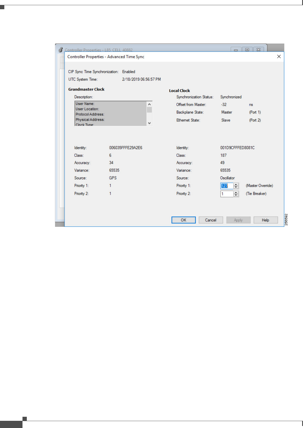
Figure 3-2 PAC Date and Time Configuration
The Advanced button allows you to configure the priority1 and priority2 values of the controller. These
values will vary depending on if the controller is designated to be a member of the grandmaster tier or
controller tier.
3-4
Deploying Scalable Time Distribution within a Converged Plantwide Ethernet Architecture
ENET-TD016A-EN-P
Chapter 3 CPwE Scalable Time Distribution Configuration
Industrial Ethernet Switches
Figure 3-3 PAC PTP Advanced Configuration
Communication Adapters
It is important to configure the communication adapters to support CIP Sync. Some Rockwell Automation
platforms, such as the 5069-AEN2TR, have CIP Sync enabled by default. Other platforms, such as the
1756-EN2T family, require manual configuration to enable CIP Sync. Refer to vendor documentation for
instructions on configuring your communications adapter.
I/O Points
CIP Sync applications require configuring the individual I/O points for time stamping. The time stamping
features of the module will vary from module to module. In addition, the configuration of the I/O points may
vary depending on the module selected and the application. Refer to vendor documentation for instructions
on configuring your I/O points.
Industrial Ethernet Switches
There are three options for configuring PTP in the IES:
• Command line

3-5
Deploying Scalable Time Distribution within a Converged Plantwide Ethernet Architecture
ENET-TD016A-EN-P
Chapter 3 CPwE Scalable Time Distribution Configuration
Industrial Ethernet Switches
• Device Manager
• Studio 5000 Logix Designer
The configuration choice will depend on the IES platform selected and preferences of the installer. The
Allen-Bradley Stratix IES support all three configuration methods, while the Cisco IE IES only support
command line and Device Manager. However, not all the PTP configuration options used in this CPwE Time
solution are available in the Device Manager or Studio 5000 Logix Designer. These configuration options
must be done via the command line interface.
Note Use caution when setting the sync limit below 50,000. This setting should only be used in IACS applications
where the grandmaster has a very high-precision clock and all the IES have hardware support for PTP
enabled.
Command Line
Step 1 Configure the IES for boundary clock mode:
IES(config)#ptp mode boundary
Step 2 Configure the boundary clock to use the feedforward transfer function:
IES(config)#ptp transfer feedforward
Step 3 Configure the time properties to persist infinitely:
IES(config)#ptp time-property persist infinite
Step 4 Configure the priority1 value for the infrastructure tier:
IES(config)#ptp priority1 2
Step 5 Configure the priority2 value for the infrastructure tier:
IES(config)#ptp priotiry2 10
Step 6 Configure the interfaces to use a sync limit of 10,000:
IES(config-if)#ptp sync limit 10000
The sync limit should be configured on all boundary clock interfaces. This can either be done individually or
with the interface range configuration command.
Device Manager
PTP is configured in the Device Manager by selecting the PTP option under the Configure menu.
Step 1 Configure the IES for boundary clock mode.
Step 2 Configure the priority1 value for the infrastructure tier.
Step 3 Configure the priority2 value for the infrastructure tier.

3-6
Deploying Scalable Time Distribution within a Converged Plantwide Ethernet Architecture
ENET-TD016A-EN-P
Chapter 3 CPwE Scalable Time Distribution Configuration
Industrial Ethernet Switches
Figure 3-4 Stratix Device Manager PTP Clock Configuration
Step 4 Configure the interfaces to use a sync fault limit of 10,000.
Figure 3-5 Stratix Device Manager PTP Port Configuration
Several of the configuration items required for this CPwE Time solution can only be configured using the
command line interface.
Step 5 Configure the boundary clock to use the feedforward transfer function:
IES(config)#ptp transfer feedforward
Step 6 Configure the time properties to persist infinitely:
IES(config)#ptp time-property persist infinite

3-7
Deploying Scalable Time Distribution within a Converged Plantwide Ethernet Architecture
ENET-TD016A-EN-P
Chapter 3 CPwE Scalable Time Distribution Configuration
Industrial Ethernet Switches
Studio 5000 Logix Designer
PTP is configured in the Time Sync Configuration section of the Allen-Bradley Stratix AOP.
Step 1 Configure the IES for boundary clock mode.
Step 2 Configure the priority1 value for the infrastructure tier.
Step 3 Configure the priority2 value for the infrastructure tier.
Step 4 Configure the interfaces to use a sync fault limit of 10,000.
Figure 3-6 Stratix Studio 5000 Logix Designer PTP Configuration
Several of the configuration items required for this CPwE Time solution can only be configured using the
command line interface.
Step 5 Configure the boundary clock to use the feedforward transfer function:
IES(config)#ptp transfer feedforward
Step 6 Configure the time properties to persist infinitely:
IES(config)#ptp time-property persist infinite

A-1
Deploying Scalable Time Distribution within a Converged Plantwide Ethernet Architecture
ENET-TD016A-EN-P
APPENDIX
A
References
This appendix includes the following major topics:
• Converged Plantwide Ethernet (CPwE), page A-1
• Other References, page A-3
Converged Plantwide Ethernet (CPwE)
• Design Zone for Manufacturing-Converged Plantwide Ethernet:
http://www.cisco.com/c/en/us/solutions/enterprise/design-zone-manufacturing/landing_ettf.html
• Industrial Network Architectures-Converged Plantwide Ethernet:
http://www.rockwellautomation.com/global/products-technologies/network-technology/architectures.p
age
• Converged Plantwide Ethernet (CPwE) Design and Implementation Guide:
–
Rockwell Automation site:
http://literature.rockwellautomation.com/idc/groups/literature/documents/td/enet-td001_-en-p.pdf
–
Cisco site:
http://www.cisco.com/c/en/us/td/docs/solutions/Verticals/CPwE/CPwE_DIG.html
• Deploying A Resilient Converged Plantwide Ethernet Architecture Design and Implementation Guide:
–
Rockwell Automation site:
https://literature.rockwellautomation.com/idc/groups/literature/documents/td/enet-td010_-en-p.pdf
–
Cisco site:
http://www.cisco.com/c/en/us/td/docs/solutions/Verticals/CPwE/REP/CPwE_REP_DG.html
• Deploying Identity and Mobility Services within a Converged Plantwide Ethernet Architecture Design
and Implementation Guide:
–
Rockwell Automation site:
https://literature.rockwellautomation.com/idc/groups/literature/documents/td/enet-td008_-en-p.pdf
–
Cisco site:
https://www.cisco.com/c/en/us/td/docs/solutions/Verticals/CPwE/3-5-1/ISE/DIG/CPwE_ISE_CV
D.ht ml
• Cloud Connectivity to a Converged Plantwide Ethernet Architecture:

A-2
Deploying Scalable Time Distribution within a Converged Plantwide Ethernet Architecture
ENET-TD016A-EN-P
Appendix A References
Converged Plantwide Ethernet (CPwE)
–
Rockwell Automation site:
https://literature.rockwellautomation.com/idc/groups/literature/documents/td/enet-td017_-en-p.pdf
–
Cisco site:
https://www.cisco.com/c/en/us/td/docs/solutions/Verticals/CPwE/5-1/Cloud/DIG/CPwE_Cloud_C
onnect_CVD.html
• Securely Traversing IACS Data Across the Industrial Demilitarized Zone Design and Implementation
Guide:
–
Rockwell Automation site:
http://literature.rockwellautomation.com/idc/groups/literature/documents/td/enet-td009_-en-p.pdf
–
Cisco site:
https://www.cisco.com/c/en/us/td/docs/solutions/Verticals/CPwE/3-5-1/IDMZ/DIG/CPwE_IDMZ
_CVD.html
• Deploying Industrial Firewalls within a Converged Plantwide Ethernet Architecture Design and
Implementation Guide:
–
Rockwell Automation site:
http://literature.rockwellautomation.com/idc/groups/literature/documents/td/enet-td002_-en-p.pdf
–
Cisco site:
https://www.cisco.com/c/en/us/td/docs/solutions/Verticals/CPwE/5-0/Firewalls/DIG/CPwE-5-IFS-
DIG.html
• Deploying Network Security within a Converged Plantwide Ethernet Architecture
–
Rockwell Automation site:
https://literature.rockwellautomation.com/idc/groups/literature/documents/td/enet-td019_-en-p.pdf
–
Cisco site:
https://www.cisco.com/c/en/us/td/docs/solutions/Verticals/CPwE/5-1/Network_Security/DIG/CPw
E-5-1-NetworkSecurity-DIG.html
• Deploying Device Level Ring within a Converged Plantwide Ethernet Architecture
–
Rockwell Automation site:
https://literature.rockwellautomation.com/idc/groups/literature/documents/td/enet-td015_-en-p.pdf
–
Cisco site:
https://www.cisco.com/c/en/us/td/docs/solutions/Verticals/CPwE/5-1/DLR/DIG/CPwE-5-1-DLR-
DIG.html
• Deploying Industrial Data Center within a Converged Plantwide Ethernet Architecture
–
Rockwell Automation site:
https://literature.rockwellautomation.com/idc/groups/literature/documents/td/enet-td014_-en-p.pdf
–
Cisco site:
https://www.cisco.com/c/en/us/td/docs/solutions/Verticals/CPwE/5-1/IDC/DIG/CPwE-5-1-IDC-DI
G. h tm l
• OEM Networking within a Converged Plantwide Ethernet Architecture
–
Rockwell Automation site:
https://literature.rockwellautomation.com/idc/groups/literature/documents/td/enet-td018_-en-p.pdf
–
Cisco site:
https://www.cisco.com/c/en/us/td/docs/solutions/Verticals/CPwE/5-1/OEM/DIG/CPwE-5-1-OEM-
CRD.html


B-1
Deploying Scalable Time Distribution within a Converged Plantwide Ethernet Architecture
ENET-TD016A-EN-P
APPENDIX
B
Test Hardware and Software
Table B-1 lists the Cisco and Rockwell Automation components used in testing the CPwE Time solution.
.
Table B-1 Cisco and Rockwell Automation Components
Component Series Ve rs i on
Allen-Bradley Stratix 5410 B 15.2(6)E0a
Allen-Bradley Stratix 5400 15.2(6)E0a
Allen-Bradley Stratix 5700 15.2(6)E0a
1756-TIME B 3.004
1756-L85E B 30.011
1756-L75 B 30.012
1756-EN2TR C 10.01
1756-IB16IEF A 1.011
1756-OB16IEF A 2.011
5069-L340DERM A 30.011
5069-AEN2TR A 3.011
5069-IB16F A 2.012
5069-OB16F A 2.012
Studio 5000 Logix Designer v30

C-1
Deploying Scalable Time Distribution within a Converged Plantwide Ethernet Architecture
ENET-TD016A-EN-P
APPENDIX
C
Acronyms
Table C-1 lists the acronyms and initialisms commonly used in CPwE documentation.
.
Table C-1 Acronyms and Initialisms
Term Description
1:1 One-to-One
AAA Authentication, Authorization, and Accounting
AD Microsoft Active Directory
AD CS Active Directory Certificate Services
AD DS Active Directory Domain Services
AES Advanced Encryption Standard
ACL Access Control List
AH Authentication Header
AIA Authority Information Access
AMP Advanced Malware Protection
ASDM Cisco Adaptive Security Device Manager
ASIC Application Specific Integrated Circuit
ASR Cisco Aggregation Services Router
BYOD Bring Your Own Device
CA Certificate Authority
CDP CRL Distribution Points
CIP ODVA, Inc. Common Industrial Protocol
CLI Command Line Interface
CoA Change of Authorization
CoS Class of Service
CPwE Converged Plantwide Ethernet
CRD Cisco Reference Design
CRL Certificate Revocation List
CSR Certificate Signing Request
CSSM Cisco Smart Software Manager
CTL Certificate Trust List
CUR Coarse Update Rate
CVD Cisco Validated Design

C-2
Deploying Scalable Time Distribution within a Converged Plantwide Ethernet Architecture
ENET-TD016A-EN-P
Appendix C Acronyms
DACL Downloadable Access Control List
DC Domain Controller
DHCP Dynamic Host Configuration Protocol
DIG Design and Implementation Guide
DLR Device Level Ring
DMVPN Dynamic Multipoint Virtual Private Network
DNS Domain Name System
DPI Deep Packet Inspection
DSRM Directory Services Restoration Mode
EAP Extensible Authentication Protocol
EAP-TLS Extensible Authentication Protocol-Transport Layer Security
EIGRP Enhanced Interior Gateway Routing Protocol
EMI Enterprise Manufacturing Intelligence
EoIP Ethernet over IP
ERP Enterprise Resource Planning
ESP Encapsulating Security Protocol
ESR Embedded Services Router
FIB Forwarding Information Base
FIFO First-In First-Out
FPGA Field-Programmable Gate Array
FQDN Fully Qualified Domain Name
FVRF Front-door Virtual Route Forwarding
GNSS Global Navigation Satellite Systems
GRE Generic Routing Encapsulation
HMAC Hash Message Authentication Code
HMI Human-Machine Interface
HSRP Hot Standby Router Protocol
IACS Industrial Automation and Control System
ICS Industrial Control System
IDMZ Industrial Demilitarized Zones
IES Industrial Ethernet Switch (Allen-Bradley Stratix, Cisco IE)
IGMP Internet Group Management Protocol
IIoT Industrial Internet of Things
IKE Internet Key Exchange
I/O Input/Output
IoT Internet of Things
IP Internet Protocol
IPDT IP Device Tracking
ISAKMP Internet Security Association and Key Management Protocol
ISP Internet Service Provider
ISE Cisco Identity Services Engine
ISR Integrated Service Router
IT Information Technology
LBS Location Based Services
Table C-1 Acronyms and Initialisms (continued)
Term Description

C-3
Deploying Scalable Time Distribution within a Converged Plantwide Ethernet Architecture
ENET-TD016A-EN-P
Appendix C Acronyms
LWAP Lightweight Access Point
MAB MAC Authentication Bypass
MAC Media Access Control
MDM Mobile Device Management
ME FactoryTalk View Machine Edition
mGRE Multipoint Generic Routing Encapsulation
MLS Multilayer Switching QoS
MMC Microsoft Management Console
MnT Monitoring Node
MPLS Multiprotocol Label Switching
MQC Modular QoS CLI
MSE Mobile Service Engine
MSS Maximum Segment Size
MTTR Mean Time to Repair
MTU Maximum Transmission Unit
NAC Network Access Control
NAT Network Address Translation
NDES Network Device Enrollment Service
NHRP Next Hop Routing Protocol
NOC Network Operation Center
NPS Microsoft Network Policy Server
NSP Native Supplicant Profile
NTP Network Time Protocol
OCSP Online Certificate Status Protocol
OEE Overall Equipment Effectiveness
OEM Original Equipment Manufacturer
OT Operational Technology
OTA Over-the-Air
OU Organizational Unit
PAC Programmable Automation Controller
PAN Policy Administration Node
PAT Port Address Translation
PCS Process Control System
PEAP Protected Extensible Authentication Protocol
PKI Public Key Infrastructure
pps Packet per second
PSK Pre-Shared Key
PSN Policy Service Node
PTP Precision Time Protocol
QoS Quality of Service
RA Registration Authority
RADIUS Remote Authentication Dial-In User Service
RAS Remote Access Server
RD Route Descriptor
Table C-1 Acronyms and Initialisms (continued)
Term Description

C-4
Deploying Scalable Time Distribution within a Converged Plantwide Ethernet Architecture
ENET-TD016A-EN-P
Appendix C Acronyms
RDG Remote Desktop Gateway
RDP Remote Desktop Protocol
RDS Remote Desktop Services
REP Resilient Ethernet Protocol
RPI Request Packet Interval
RTT Round Trip Time
SA Security Association
SaaS Software-as-a-Service
SCEP Simple Certificate Enrollment Protocol
SE FactoryTalk View Site Edition
SHA Secure Hash Standard
SIG Secure Internet Gateway
SPW Software Provisioning Wizard
SSID Service Set Identifier
STP Spanning-Tree Protocol
SYN Synchronization
TAI International Atomic Time
TCN Topology Change Notification
TCP Transmission Control Protocol
TLS Transport Layer Security
UDP User Datagram Protocol
UTC Coordinated Universal Time
VLAN Virtual Local Area Network
VM Virtual Machine
VNC Virtual Network Computing
VPN Virtual Private Network
VRF Virtual Route Forwarding
VSS Virtual Switching System
WA N Wide Area Network
wIPS wireless Intrusion Prevention Service
WLAN Wireless LAN
WLC Cisco Wireless LAN Controller
WSA Cisco Web Security Appliance
ZFW Zone-Based Policy Firewall
Table C-1 Acronyms and Initialisms (continued)
Term Description

D-1
Deploying Scalable Time Distribution within a Converged Plantwide Ethernet Architecture
ENET-TD016A-EN-P
APPENDIX
D
About the Cisco Validated Design (CVD)
Program
Converged Plantwide Ethernet (CPwE) is a collection of tested and validated architectures developed by
subject matter authorities at Cisco and Rockwell Automation with assistance by Panduit which follows the
Cisco Validated Design (CVD) program.
CVDs provide the foundation for systems design based on common use cases or current engineering system
priorities. They incorporate a broad set of technologies, features, and applications to address customer needs.
Each one has been comprehensively tested and documented by engineers to help achieve faster, more reliable,
and fully predictable deployment.
The CVD process is comprehensive and focuses on solving business problems for customers and
documenting these solutions. The process consists of the following steps:
• Requirements are gathered from a broad base of customers to devise a set of use cases that will fulfill
these business needs.
• Network architectures are designed or extended to provide the functionality necessary to enable these use
cases, and any missing functionality is relayed back to the appropriate product development team(s).
• Detailed test plans are developed based on the architecture designs to validate the proposed solution, with
an emphasis on feature and platform interaction across the system. These tests generally consist of
functionality, resiliency, scale, and performance characterization.
• All parties contribute to the development of the CVD guide, which covers both design recommendations
and implementation of the solution based on the testing outcomes.
Within the CVD program, Cisco also provides Cisco Reference Designs (CRDs) that follow the CVD process
but focus on reference designs developed around specific sets of priority use cases. The scope of CRD testing
typically focuses on solution functional verification with limited scale.
For more information about the CVD program, please see the Cisco Validated Designs at the following URL::
https://www.cisco.com/c/en/us/solutions/enterprise/validated-design-program/index.html

D-2
Deploying Scalable Time Distribution within a Converged Plantwide Ethernet Architecture
ENET-TD016A-EN-P
Appendix D About the Cisco Validated Design (CVD) Program
.
Panduit Corp. is a world-class provider of engineered, flexible, end-to-end electrical and network connectivity infrastructure solutions that provides businesses with the ability to keep pace
with a connected world. Our robust partner ecosystem, global staff, and unmatched service and support make Panduit a valuable and trusted partner.
www.panduit.com
US and Canada:
Panduit Corp.
World Headquarters
18900 Panduit Drive
Tinley Park, IL 60487
Tel. 708.532.1800
Asia Pacific:
One Temasek Avenue #09-01
Millenia Tower
039192 Singapore
Tel. 65 6305 7555
Europe/Middle East/Africa:
Panduit Corp.
West World
Westgate London W5 1XP Q
United Kingdom
Tel. +44 (0) 20 8601 7219
Latin America:
Panduit Corp.
Periférico Pte Manuel Gómez
Morin #7225 - A
Guadalajara Jalisco 45010
MEXICO
Tel. (33) 3777 6000
Cisco is the worldwide leader in networking that transforms how people connect, communicate and collaborate. Information about Cisco can be found at www.cisco.com. For ongoing news,
please go to http://newsroom.cisco.com. Cisco equipment in Europe is supplied by Cisco Systems International BV, a wholly owned subsidiary of Cisco Systems, Inc.
www.cisco.com
Americas Headquarters
Cisco Systems, Inc.
San Jose, CA
Asia Pacific Headquarters
Cisco Systems (USA) Pte. Ltd.
Singapore
Europe Headquarters
Cisco Systems International BV
Amsterdam, The Netherlands
Cisco has more than 200 offices worldwide. Addresses, phone numbers, and fax numbers are listed on the Cisco Website at www.cisco.com/go/offices.
Cisco and the Cisco logo are trademarks or registered trademarks of Cisco and/or its affiliates in the U.S. and other countries. To view a list of Cisco trademarks, go to this URL:
www.cisco.com/go/trademarks. Third-party trademarks mentioned are the property of their respective owners. The use of the word partner does not imply a partnership relationship between
Cisco and any other company. (1721R)
Rockwell Automation is a leading provider of power, control and information solutions that enable customers to be more productive and the world more sustainable. In support of smart
manufacturing concepts, Rockwell Automation helps customers maximize value and prepare for their future by building a Connected Enterprise.
www.rockwellautomation.com
Americas:
Rockwell Automation
1201 South Second Street
Milwaukee, WI 53204-2496 USA
Tel: (1) 414.382.2000
Fax: (1) 414.382.4444
Asia Pacific:
Rockwell Automation
Level 14, Core F, Cyberport 3
100 Cyberport Road, Hong Kong
Tel: (852) 2887 4788
Fax: (852) 2508 1846
Europe/Middle East/Africa:
Rockwell Automation
NV, Pegasus Park, De Kleetlaan 12a
1831 Diegem, Belgium
Tel: (32) 2 663 0600
Fax: (32) 2 663 0640
Allen-Bradley, ControlLogix, FactoryTalk, Integrated Architecture, Logix PAC, Rockwell Automation, Stratix, and Studio 5000 Logix Designer are trademarks of Rockwell Automation, Inc.
Trademarks not belonging to Rockwell Automation are property of their respective companies.
CIP, CIP Sync, and EtherNet/IP are trademarks of the ODVA, Inc.
Microsoft is a trademark of Microsoft Corporation.
© 2019 Cisco Systems, Inc., Panduit Corp. and Rockwell Automation, Inc. and all rights reserved.
Publication ENET-TD016A-EN-P May 2019
