
AVEVA
TM
InTouch HMI
formerly Wonderware
Getting Started Guide
© 2020 AVEVA Group plc and its subsidiaries. All rights reserved.
No part of this documentation shall be reproduced, stored in a
retrieval system, or transmitted by any means, electronic,
mechanical, photocopying, recording, or otherwise, without the
prior written permission of AVEVA. No liability is assumed with
respect to the use of the information contained herein.
Although precaution has been taken in the preparation of this
documentation, AVEVA assumes no responsibility for errors or
omissions. The information in this documentation is subject to
change without notice and does not represent a commitment on
the part of AVEVA. The software described in this documentation is
furnished under a license agreement. This software may be used or
copied only in accordance with the terms of such license
agreement.
ArchestrA, Aquis, Avantis, Citect, DYNSIM, eDNA, EYESIM, InBatch,
InduSoft, InStep, IntelaTrac, InTouch, OASyS, PIPEPHASE, PRiSM,
PRO/II, PROVISION, ROMeo, SIM4ME, SimCentral, SimSci, Skelta,
SmartGlance, Spiral Software, Termis, WindowMaker,
WindowViewer, and Wonderware are trademarks of AVEVA and/or
its subsidiaries. An extensive listing of AVEVA trademarks can be
found at: https://sw.aveva.com/legal. All other brands may be
trademarks of their respective owners.
Contact Information
AVEVA Group plc High Cross Madingley Road Cambridge CB3 0HB. UK
https://sw.aveva.com/
For information on how to contact sales, customer training, and
technical support, see https://sw.aveva.com/contact.
Publication Date: December 2020

3
Contents
Welcome to InTouch HMI ......................................................................... 5
Installing InTouch HMI .................................................................................. 5
InTouch HMI Licensing.................................................................................. 5
Working with InTouch HMI....................................................................... 7
Comparing Different Types of InTouch HMI Applications .............. 8
Creating Standalone Applications............................................................ 9
Adding Industrial Graphics to Applications......................................9
Migrating Existing Modern Applications .........................................10
Creating Managed Applications .............................................................10
Integrating Application Objects with InTouch HMI .....................12
Working with the Industrial Graphic Editor ....................................12
Connectivity with Gateway Communication Driver and OPC ......14
InTouch HMI as a OPC UA Server...........................................................14
Creating Standalone Applications......................................................... 15
Creating a Standalone Application ........................................................15
Editing a Standalone Application ...........................................................16
Adding Symbols to a Window .............................................................17
Creating InTouch HMI Tags ...................................................................19
Creating a Window Script......................................................................21
Configuring Symbols...............................................................................23
Changing Symbol Labels........................................................................27
Running a Standalone Application ........................................................29
Creating Managed Applications............................................................ 31
Starting the IDE..............................................................................................32
Starting the IDE from the Start Menu ...............................................32
Creating a Galaxy ..........................................................................................32
Deploying Your Application Objects .....................................................34
Editing a Managed Application...............................................................36
Embedding Industrial Graphics into an InTouch HMI Managed
Application Window ................................................................................38

4 Contents
Connecting Attributes to an Industrial Graphic................................39
Viewing InTouch HMI Applications Remotely ...................................42
InTouch Access Anywhere......................................................................42
InTouch Web Client ..................................................................................43
Getting More Information.......................................................................45

5
Welcome to InTouch HMI
AVEVA InTouch HMI, formerly Wonderware continues the
tradition of market leadership in Human Machine Interface
(HMI) applications. This booklet gives you a quick overview of
the major features of InTouch HMI and explains the essential
tasks to create several types of InTouch HMI applications.
Installing InTouch HMI
The simplified installation process makes installing InTouch
HMI easier than ever.
The major decision you must make when you install InTouch
HMI is whether to install the InTouch HMI development and
run-time components, or the run-time components alone.
The installation program guides you in selecting the features
you want, verifying or modifying your selections, installing
prerequisite software, and then installing InTouch HMI. For
detailed information about installation, refer to the System
Platform Installation Guide.
InTouch HMI Licensing
A valid product license is required to enable InTouch HMI
functionality. The AVEVA License Server and AVEVA License
Manager are automatically selected when you select InTouch
HMI during installation.
Note If you are using a workgroup, the AVEVA License
Manager and License Server must be installed on the same
node.
You will need to activate your InTouch HMI licenses before
using WindowMaker or WindowViewer. For detailed
information about license activation, refer to the AVEVA

6 Welcome to InTouch HMI
Enterprise Licensing Guide. It is also available on the AVEVA
License Manager node as a PDF file, under the AVEVA start
directory, after installation is complete.

7
Working with InTouch HMI
An InTouch HMI application shows a graphical representation
of a manufacturing or process environment. The tools,
materials, and processes used to create a product appear as
visual elements in an application’s windows. This chapter
describes the steps to create the following types of InTouch
HMI applications:
• Standalone Applications
• Managed Applications

8 Working with InTouch HMI
Comparing Different Types of InTouch HMI
Applications
The following table shows some major similarities and
differences between different types of InTouch HMI
applications.
Tasks
Types of InTouch HMI Applications
Standalone Managed
Main Use Tag based, native
symbols and Industrial
graphics
Object based and
Industrial Graphics
Create an
Application
Application Manager IDE
• New applications
• Import standalone
applications
• Import
SmartSymbols
Edit an
Application
WindowMaker started
from Application
Manager
WindowMaker started
from the IDE
Delete an
Application
Delete folder and
remove from
Application Manager
Delete InTouchViewApp
template
Publish an
Application
Yes, from
WindowMaker
Yes, from IDE
Create Industrial
Graphics
Yes Yes
Incorporate
Industrial
Graphics
Yes, can be added,
edited, and viewed from
an application
Yes, can be added,
edited, and viewed from
the IDE
Incorporate
Application
Objects
No Yes

Creating Standalone Applications 9
Creating Standalone Applications
The following figure shows the components that you would
use to create, manage, build and run standalone InTouch HMI
applications.
Use InTouch HMI Application Manager to create and manage
standalone applications. You can build standalone applications
with WindowMaker and run them from WindowViewer.
Standalone applications give you the capability to easily
integrate Industrial Graphics directly into your applications.
You can switch between WindowMaker and WindowViewer to
test or run your applications and switch back to make
modifications to your applications.
Adding Industrial Graphics to Applications
After you have created an application, WindowMaker’s
Industrial Graphic Toolbox includes separate folders
containing the Industrial Graphic Library and Situational
Awareness Library of predefined symbols. The Industrial
Graphic ibrary contains realistic symbols of standard industrial
objects.
Situational Awareness Library symbols are configurable
symbols designed to enhance an operator's situational
awareness of current process conditions using highly efficient
visual techniques and best practices.

10 Working with InTouch HMI
Situational Awareness Library symbols have a
simplified look and provide minimum visual
detail to efficiently convey their functional
purpose and status without showing irrelevant
information to operators.
Most Situational Awareness Library symbols
are designed as Symbol Wizards that
incorporate multiple visual and functional configurations in
each symbol. Selecting a configuration for a symbol is a simple
matter of selecting options from a list without the burden of
extensive design work. Also, Situational Awareness Library
symbols provide faster application run-time performance
because of their lightweight design and simple appearance.
Migrating Existing Modern Applications
In System Platform 2020, the functionality of modern
applications has been merged to the new Standalone
application. For detailed instructions to migrate existing
modern application, see the InTouch HMI Application
Management and Extension Guide.
Creating Managed Applications
InTouch HMI shares the Integrated Development Environment
(IDE) with Application Server. You can also create Managed
InTouch applications from the IDE using Industrial Graphics
and automation objects.
The IDE includes a suite of graphic tools and automation
objects to build simple or complex system environments.
Using automation objects, you can integrate your InTouch HMI
applications much more easily into the System Platform. Also,
you can embed pre-built Industrial Graphics and Situational
Awareness Library symbols into your applications or use a
wide assortment of tools from the Industrial Graphic Toolbox
to create your own symbols.
Using the IDE to manage your InTouch applications, you can:
• View which applications are running on individual Galaxy
nodes.
• Use a central repository to manage applications.

Creating Managed Applications 11
• Deploy application changes to WindowViewer nodes
running InTouch applications.
The following figure shows the integration of the IDE with
traditional InTouch HMI components. The figure shows the
steps to create a managed InTouch HMI application with the
IDE.
1 Create a managed InTouch application in the IDE by
deriving a template from the $InTouchViewApp base
template.
You create a managed application on one node of the
Galaxy with WindowMaker. Then, you deploy it to one or
more target nodes running WindowViewer.
2 Open the managed application in WindowMaker.
3 Develop your InTouch application in WindowMaker. If
needed, switch to WindowViewer to test the application.
4 Save the changes to the InTouch application.
5 Derive an instance of the managed application and select
the nodes to deploy the application.

12 Working with InTouch HMI
6 Deploy the InTouch application to the target nodes
running WindowViewer in the Galaxy.
7 Run the application in WindowViewer on target nodes.
Integrating Application Objects with InTouch HMI
A Galaxy is your specific production environment to run your
managed InTouch HMI applications. A Galaxy includes all
computers and components. It is a collection of platforms,
engines, application objects, templates, instances, and
attributes you define as the parts of your specific application.
This collection is stored in a Galaxy database on a node called
the Galaxy Repository (GR).
Application Server manages your InTouch applications with a
specific type of application object called the InTouchViewApp
application object, which is derived from the
$InTouchViewApp base template.
After you derive a new InTouchViewApp template from the
$InTouchViewApp base template, you can associate the
InTouchViewApp template with an InTouch application by:
• Creating a new InTouch application.
• Importing a standalone InTouch application.
An InTouchViewApp template represents one specific InTouch
application at design time and cannot be executed at run time.
You deploy an instance of your derived InTouchViewApp
template to a target node to run your InTouch applications.
The target node is the node on which the managed InTouch
application can run in WindowViewer. To distribute your
InTouch application, you can create multiple instances of the
same InTouchViewApp template and deploy them to multiple
nodes.
Working with the Industrial Graphic Editor
You can create Industrial Graphics from basic elements such as
rectangles, lines, circles, or text much like graphics created
from WindowMaker. The Industrial Graphic Editor also
includes other graphic tools to create more complex drawing
elements like closed curves, chords, and Windows controls.

Creating Managed Applications 13
Industrial Graphics are graphics
you can add to an application
window to visualize data in a
production process. You create
Industrial Graphics in the
Industrial Graphic Editor. You
select a basic graphical object
called an element from the Tools
panel and place it on the drawing
area called the canvas. Then, you can change the appearance
of your drawn elements either by accessing their properties
directly, or by modifying their physical appearance. You can
configure the elements or the symbol with animations.
The following figure shows the various tools and palettes of
the Industrial Graphic Editor that you use to create and
customize symbols
.
When you embed an Industrial Graphic into an InTouch HMI
window and the symbol is contained in an Automation
template, you can easily create a new instance of the
Automation object. The embedded symbol automatically
references the new object.

14 Working with InTouch HMI
After you build your managed application from the IDE, you
can publish it. A published InTouch application is no longer
associated with the InTouchViewApp template and cannot be
edited from the IDE. But, a published InTouch application can
still communicate with the Galaxy by any embedded Industrial
Graphic. You can write data back to the Galaxy or visualize
Galaxy data with the Industrial Graphic.
Connectivity with Gateway Communication Driver
and OPC
Gateway Communication Driver is included with the InTouch
HMI. When the InTouch HMI is installed, an InTouch Access
Name is created for Gateway Communication Driver, pointing
by default to the localhost.
Gateway Communication Driver streamlines OLE for Process
Control (OPC) and OPC Unified Architecture (OPC UA) setup,
enhancing device integration. OI Server Manager also is
included, providing the System Management Console (SMC)
as an interface for configuring the Gateway Communication
Driver and OPC.
Gateway Communication Driver requires configuration using
the SMC. OPC and OPC UA Servers require a separate
installation.
InTouch HMI as an OPC UA Server
InTouch HMI can be configured to act as an OPC UA server
allowing clients to connect and access tag data. For more
information, refer to the InTouch HMI help.

Creating a Standalone Application 15
Creating Standalone
Applications
All configuration steps to use Industrial Graphics are
completed from InTouch WindowMaker. You do not need to
use the IDE to create a standalone application. When you are
creating a window for an application, you simply drag
Industrial Graphics or Situational Awareness Library symbols
directly from WindowMaker’s Industrial Graphic Toolbox into a
window.
Creating a Standalone Application
You create a Standalone InTouch HMI application from InTouch
Application Manager.
To create a standalone application
1 Click Start on your Windows desktop and search for
InTouch Application Manager.
2 Select New by using one of the following methods:
a Select
New from the File menu.
b Right-click within Application Manager and select
New
from the shortcut menu.
c Select the New icon from the menu bar.
d Press the Ctrl + N keys.
The
Create New Application wizard appears.
3 Select a
Template, and click Next >.
The Enter Application Details page displays the fields
to enter the application name, directory name, application
path, application target resolution and description.
4 Enter the details and specify a target resolution if different
than the default screen resolution. Name the application
Chocolate Milk.
a Select from a list of predefined target resolutions or
select Custom. The Pixel width and height fields
become editable. .
5 Click Finish.
16 Creating Standalone Applications
After an application is created, it appears in Application
Manager’s list of applications. The Application Type column
identifies the application as Standalone.
Editing a Standalone Application
You open a standalone application from the InTouch
Application Manager and edit it in WindowMaker.
This section demonstrates the basic steps to build an
application. The following figure shows a window from a
simple application that combines and mixes the ingredients to
make chocolate milk. Complete the procedures in this section
to learn the over all workflow to build an application.
In the window, the Alarm Viewer control and the lines that
represent pipes are traditional InTouch HMI graphic elements.
All other graphics elements shown in the window are Industrial
Graphics or Situational Awareness library symbols.

Editing a Standalone Application 17
To edit an application
1 Open InTouch Application Manager.
2 Double-click on the Chocolate Milk application to edit it.
The first time you open an InTouch HMI application in
WindowMaker no windows have been created.
3 Right-click on
Windows in the Windows & Scripts area
of WindowMaker and select
New Window from the
shortcut menu.
4 Assign “Mixing Station” as the name of the window in the
Name field of the Window Properties dialog box.
5 Set the width and height of the window by entering values
in the
Window Width and Window Height fields.
6 Change the default background of the window to a lighter
color by clicking Window Color and selecting a color
from the Standard Palette.
7 Click
OK.
The window you created appears in WindowMaker.
Continue with the next procedure to add symbols to the
window.
Adding Symbols to a Window
Drag and drop graphics from the Industrial Graphic Toolbox to
add symbols to a window.
This procedure explains how to add the following symbols to
the window you created earlier:
• Situational Awareness Library
• 3 valves (Valves folder, SA_Valve_2Way)
• 1 vessel (Equipment folder, SA_Tank_Vessel)

18 Creating Standalone Applications
• 1 meter (Meters folder, SA_Meters)
• 1 simple trend (TrendPen folder, SA_Trend)
• 1 agitator (Equipment folder, SA_Agitator_Settler)
• Industrial Graphic Library
• 3 rocker switches (Switch folder, RockerSwitch)
• InTouch Wizards
• 1 alarm viewer control (AlarmViewerCtrl)
• InTouch Graphic Toolbar
• 3 lines that represent pipes
To add symbols to an Application
1 If necessary, open the Mixing Station window you created
in WindowMaker.
2 Expand the Situational Awareness Library folder in the
Industrial Graphic Toolbox to show the list of folders.
3 Open the
Valves folder and select the SA_ISA_2WValve
symbol.
4 Keeping your left mouse key pressed, drag the symbol to
the open window and release the key at the approximate
location where you want to place the symbol.
5 Select the symbol and place it precisely where you want it
to appear in the window.
6 Repeat steps 3-5 and add the remaining Industrial
Graphics and Situational Awareness Library symbols listed
on the previous page.
The list of symbols on the previous page includes the
folders in the Industrial Graphic Toolbox where the
symbols are located.
7 Click the
Wizards icon from the WindowMaker menu bar
and select AlarmViewerCtrl from the
ActiveX Controls
group.
8 Click
OK and place the Alarm Viewer control near the top
of the window.
9 Select the Line tool from the WindowMaker graphic tool
bar.

Editing a Standalone Application 19
10 Draw three lines that represent the two input pipes and the
output pipe.
11 Click
Line from the menu bar and select a thicker line type
to make your lines look more like pipes.
12 Arrange the graphic elements on your window to look like
the following example of a chocolate milk mixing station.
Creating InTouch HMI Tags
InTouch HMI applications represent an industrial process using
data associated with InTouch HMI tags.
In this simple application, tag data will be shown or used to set
the state of the symbols that represent the equipment of a
mixing station.
This procedure explains how to create the following tags for a
mixing station application:
Tag Tag Type
Symbol
Association
Tank_Level Memory Integer Mixing Tank
Valve_Chocolate Memory Discrete Chocolate Valve

20 Creating Standalone Applications
To create InTouch HMI tags
1 On the Special menu, click Tagname Dictionary.
2 Click
New. The Tagname field clears.
3 Type Tank_Level in the Tagname field.
4 Click
Type to show the various types of InTouch HMI tags.
5 Select
Memory Integer as the type of tag.
6 Click Alarms near the top of the Tagname Dictionary to
expand the dialog box to show fields to set alarm
conditions.
7 Select High and set 1400 in the Alarm Value field.
8 Click Save.
9 Repeat steps 2-4 to create the three valve tags.
a Enter the name of the valve tag in the
Tagname field.
b Set the tag type to Memory Discrete for all three valve
tags.
Valve_Milk Memory Discrete Milk Valve
Valve_Outlet Memory Discrete Outlet Valve
Agitator_RPM Memory Integer Tank Agitator
Tag Tag Type
Symbol
Association

Editing a Standalone Application 21
c Click Save to save each valve tag.
10 Create the Agitator_RPM tag using the same steps (2-8)
used to create the Tank_Level tag.
a Enter Agitator_RPM as the name of the tag.
b Set the tag type to Memory Integer.
c Select
High and set the Alarm Value field to 1500.
Creating a Window Script
A window script sets the operating conditions of the
Chocolate Milk application while it is running in
WindowViewer:
• When the Chocolate or Milk valves are open and the
Outlet valve is closed, the tank fills with ingredients.
• When the Chocolate or Milk valves are open and the
Outlet valve is open, the tank volume remains constant.
• When the Chocolate and Milk valves are closed and the
Outlet valve is open, the chocolate milk empties from the
tank.
• When the mixing tank level is less than 1500 liters and the
chocolate or milk values are open, the tank begins to fill
with ingredients.

22 Creating Standalone Applications
• When is the tank level is greater than 500 liters and the
outlet valve is closed, the agitator begins to rotate.
• When the tank level falls to less than 500 liters and the
outlet valve is open, the agitator stops.
To create a window script
1 Right-click on a blank area of the Mixing Station window to
show a shortcut menu.
2 Select
Window Scripts from the shortcut menu.
3 Type or copy the following windows script into the Scripts
dialog box.
4 Set the Condition Type field to While Showing.
5 Set the
Every field to a value between 500-700
milliseconds.
The window script will run periodically at the interval you
set in the Every field.
6 Click
Validate to see if there are any errors in the script.
7 Correct any script errors and click
OK.

Editing a Standalone Application 23
Configuring Symbols
Industrial Graphics contain custom properties that extend the
standard properties of a symbol. In this sample application,
you must assign tags to custom properties to show the current
value of a tag or set the states when the equipment
represented by a symbol is active or inactive.
Most Situational Awareness Library symbols are also Symbol
Wizards. In addition to custom properties, Symbol Wizards
contain Wizard Options to configure their appearance and
functionality.
This procedure explains how to assign values to the custom
properties and Wizard Options listed in the following tables.

24 Creating Standalone Applications
Symbol Custom Properties
Symbol Wizards
Symbol Custom Property Assigned Values
Chocolate
Rocker Switch
Value Valve_Chocolate
Milk Rocker
Switch
Value Valve_Milk
Outlet Rocker
Switch
Value Valve_Outlet
Chocolate Valve EquipmentStateActive Valve_Chocolate
Milk Valve EquipmentStateActive Valve_Milk
Outlet Valve EquipmentStateActive Valve_Outlet
Mixing Tank LabelVisible True
Tank Agitator PV Agitator_RPM
PVRangeFullScaleMax 3000
PVRangeFullScaleMin 0
Tank Volume
Meter
PV Tank_Level
PVRangeFullScaleMax 1500
PVRangeFullScaleMin 0
Tank Volume
Trend
Pen Tank_Level
Pen_RangeFullScaleMax 1500
Pen_RangeFullScaleMin 0
Alarm Client None N/A
Symbol Wizards Wizard Options
Assigned
Values
Chocolate Rocker
Switch
None-Industrial Graphics N/A
Milk Rocker Switch None-Industrial Graphics N/A

Editing a Standalone Application 25
To configure custom properties and Wizard Options
1 Double-click on the Chocolate rocker switch to show the
Edit Symbol Properties dialog box.
Outlet Rocker
Switch
None-Industrial Graphics N/A
Chocolate Valve ActuatorType Digital
Milk Valve ActuatorType Digital
Outlet Valve ActuatorType Digital
Mixing Tank QualityStatusIndicator False
Tank Agitator PVNumericDisplay True
EngUnits True
EngUnitsType StaticText
QualityStatusIndicator False
Tan k Vol ume
Meter
Type Level
Tan k Vol ume
Trend
SymbolMode Advanced
YAxisRangeType ClipOutOf
RangeValues
PlotType Line
Label True
LabelType StaticText
GridVerticalTimePeriod
Scale
True
GridVerticalTimePeriodSc
aleUnits
True
TimePeriod True
Alarm Client None N/A
Symbol Wizards Wizard Options
Assigned
Values

26 Creating Standalone Applications
2 Select Value from the Name field.
3 Click the
Browse button at the right of the Default Value
field to show the
Select Tag dialog box.
4 Select the
Valve_Chocolate tag and click OK.
The current value of the Valve_Chocolate tag is associated
to the Chocolate rocker switch’s Value custom property.
5 Repeat steps 1-4 for the other two rocker switch symbols
and assign the tag shown in the Symbol Custom Properties
table to each symbol’s Value custom property.
6 Double-click on the Chocolate valve to show the
Edit
Symbol Properties
dialog box.

Editing a Standalone Application 27
7 Using steps 1-4, assign the Valve_Chocolate tag to the
symbol’s EquipStateActive custom property.
8 Click the
Wizard Options tab.
9 Select ActuatorType from the Name field.
10 Set the
Value field to Digital and click OK.
11 Repeat steps 1-10 and assign values to the custom
properties and Wizard Options of the remaining symbols
of the Chocolate Milk application.
Changing Symbol Labels
The Symbol Wizards used in the Chocolate Milk application
have their Label Wizard Option set to True and the LabelType
Wizard Option set to StaticText. With this symbol
configuration, you can use the InTouch Substitute Strings
function to assign a visible static label for the symbols in the
Mixing Station window.
Symbol Current String
Application
Label
Chocolate Valve Label Chocolate
Milk Valve Label Milk
Outlet Valve Label Outlet
Mixing Tank Label Chocolate Milk
Agitator Label Agitator
EU RPM
Tan k Mete r La bel Tank Volume
EU Liters
Trend Label Tank Volume

28 Creating Standalone Applications
To change symbol labels
1 Right-click on the Chocolate valve symbol to show the
shortcut menu.
2 Select
Substitute and Substitute Strings from the
shortcut menu.
The Substitute Strings dialog box appears with fields to
substitute the current strings of the symbol.
3 Type Chocolate in the Label field and click OK.
The Chocolate label appears above the valve symbol.
4 Repeat steps 1-3, to assign labels to the remaining
symbols you added to the Mixing Station window.

Running a Standalone Application 29
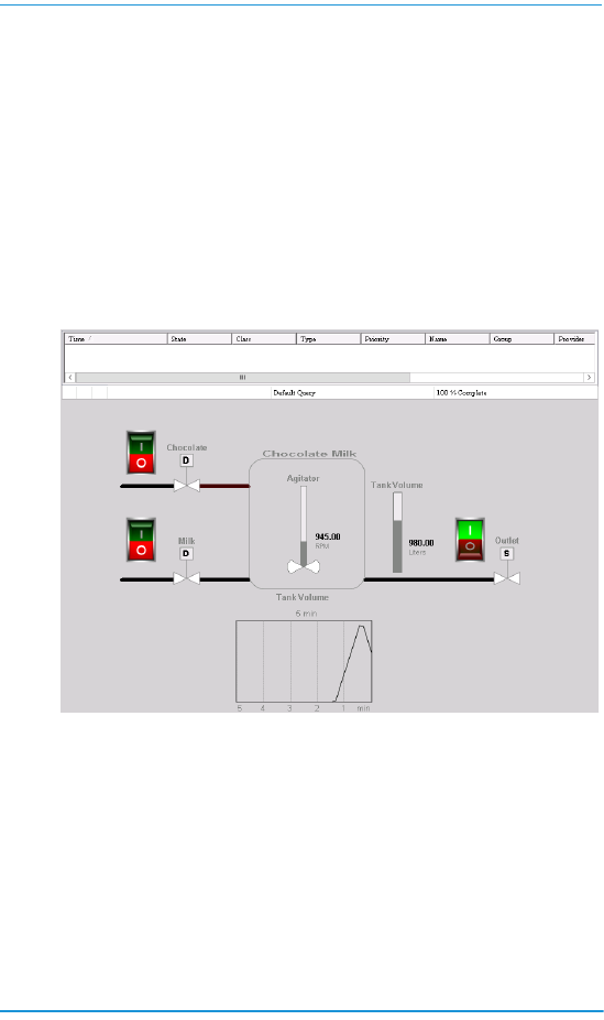
Running a Standalone Application
You view a running application from WindowViewer. After you
have finished, your Mixing Station window should look like the
following example.
In this example, a window script begins running when viewing
the application. The script assigns states and values to the
assigned InTouch HMI tags associated with the symbols shown
in the application’s window.
The following example shows the Chocolate Milk application
immediately after starting it in WindowViewer. All of the valves
are closed and the mixing tank is empty.

30 Creating Standalone Applications
Typically, Situational Awareness Library symbols use fill
shading to indicate their current state. Open the Chocolate or
Milk valve by selecting a rocker switch. Notice the change in
the fill color that indicates the valve is open. Also, the fill color
of the agitator and meter symbols change to indicate they are
in an active state or showing a value.
When the tank volume reaches 500
liters, the agitator starts, and its
current RPM appears next to the
agitator. Alarms occur if the tank
volume exceeds 1400 liters or the
agitator exceeds 1500 RPM. You manage alarms by selecting
options from the shortcut menu of the Alarm Viewer control.

7
Creating Managed
Applications
Managed applications are built using the IDE and automation
objects, in addition to the components of a Standalone
application. Each Managed application is associated with a
InTouchView App object.
When you install InTouch HMI, you can install several sample
applications. You can examine these sample applications to
understand how scripts, animations, and graphics work
together to provide a visual interface for your production
environment.
The following figure shows a portion of a window from the
InTouch HMI reactor demonstration application.
The reactor application demonstrates how you can manage an
application with the IDE and includes Industrial graphics and
objects.

8 Creating Managed Applications
The analog meter next to the product storage tank shows the
current volume of liquid stored in the tank. The meter is not
part of the standard reactor application.
This section describes the essential tasks to create a Managed
InTouch application by showing how to embed this meter into
the reactor application.
Starting the IDE
You can start the IDE from the Windows Start menu.
Starting the IDE from the Start Menu
The following procedure shows the steps to start the IDE from
a computer running Microsoft Windows 7 and later versions of
Windows.
To start the IDE from the Windows Start Menu
1 Click the Windows Start button.
2 Click the ArchestrA IDE icon from the list.
The Connect to Galaxy dialog box appears.
Creating a Galaxy
After you start the IDE, the Connect to Galaxy dialog box
appears. The first time you start the IDE you need to create a
Galaxy, which is a project database. After that, you can select
the Galaxy in which you are developing managed applications
each time you start the IDE.
To create a Galaxy
1 Start the ArchestrA IDE. The Connect to Galaxy dialog box
appears.

Creating a Galaxy 9
2 Click New Galaxy. The New Galaxy dialog box appears.
3 Complete the fields of the New Galaxy dialog box by
doing the following:
a Type the node name of the computer that serves as
the Galaxy Repository (GR). This is the computer
where the SQL Server database server is running.
b Type the name of the Galaxy that you are creating.
c Select Reactor_Demo_InTouch. cab as the type of
Galaxy from the drop-down list of the Galaxy Type
box.
This is a custom Galaxy that includes the InTouch Reactor
Demo application.
4 Click Create. The New Galaxy dialog box shows the
progress of creating a new Galaxy.
5 Click Close after the new Galaxy is created.
6 Click Connect to connect to the Galaxy you created.
The ArchestrA IDE dialog box appears.

10 Creating Managed Applications
7 Click the Template Toolbox tab.
8 If necessary, click the ReactorDemo folder to show the
objects within it.
The Template Toolbox shows the $ReactorDemo derived
template. You can use this derived template to create a
managed application or edit the application within
WindowMaker.
Note You can create a Managed InTouch HMI application
from an application template. See the InTouch HMI and
ArchestrA Integration Guide for details.
Deploying Your Application Objects
Deploying your Galaxy copies the objects from your
development environment to a run-time environment. Until
you deploy your application’s objects from the IDE, you cannot
run your Managed applications.
The pane at the bottom left of IDE includes three tabs to show
different views of your Galaxy objects. Selecting the
Deployment tab shows the current status of all objects that
are part of your application. An orange square next to an
object indicates the object is undeployed.

Deploying Your Application Objects 11
To deploy your application’s objects
1 In the Deployment pane, right click on the name of the
Galaxy at the top of the list of application objects.
2 Select Deploy from the shortcut menu.
The Deploy dialog box appears with options.
3 Accept the default options and click OK.

12 Creating Managed Applications
4 Click Close after all of your objects have been deployed.
The orange square next to each object is gone, indicating
that your application’s objects are deployed.
Editing a Managed Application
You edit a Managed InTouch application by starting
WindowMaker from the IDE.
To start WindowMaker from the IDE
1 Open the IDE.
2 Click the Template Toolbox tab to show the set of folders
containing automation objects.
3 If necessary, click on the ReactorDemo folder to expand
the list of automation objects within it. You see the
$ReactorDemo template.
4 Double-click on the $ReactorDemo template.
WindowMaker starts as the default editor. The figure
below shows WindowMaker after you initially open the
Reactor demonstration application for editing.
The Windows & Scripts area lists the windows that are
part of the Reactor demonstration application. This figure
shows the Windows to Open dialog box to select the
windows you want to edit. You may have to open the
Windows to Open dialog box. Steps 5 and 6 explain how
to open the dialog box and select the Reactor application
windows.
5 Click File, and then Open Window to show the Windows
to Open dialog box.

Editing a Managed Application 13
6 Select the Main, Menu, and Reactor Display windows
from the list and click OK. Together, these windows make
up the main Reactor demonstration screen.
The following figure shows the portion of the Reactor
Demo window containing graphics that represent the
components of a reactor.
7 Increase the text size of the OUTPUT caption to the right of
the tank by doing the following:
a Click on the OUTPUT caption to select it and show
the text box sizing handles.
b Using your mouse, click on a sizing handle and keep
the mouse button pressed.
c Move the mouse to increase the size of the text box.
d Release the mouse button when the text is the size
you want.
8 Save your changes to the window.
9 Click File, and then Exit. WindowMaker closes and you
return to the IDE. The Check In dialog box appears.

14 Creating Managed Applications
10 Type a comment if you want, and then click OK.
11 Click Close after the application is checked in.
You have made a round trip from the IDE to WindowMaker
and back to the IDE again. Now that you understand the steps
to edit a managed application from WindowMaker, the next
section explains how to embed an Industrial Graphic in an
application window.
Embedding Industrial Graphics into an InTouch
HMI Managed Application Window
You can embed an Industrial Graphic into the windows of your
Managed InTouch application. The embedded symbol appears
with its original name appended by a number. The number
increments each time you embed the same symbol again.
To embed an Industrial Graphic from the Graphic
Toolbox
1 Open the IDE.
2 Double-click on the $ReactorDemo derived template to
open it in WindowMaker.
3 Show the main Reactor window.
4 On the Edit menu, click Embed Industrial Graphic. The
Galaxy Browser appears.
5 Click the Graphic Toolbox icon. The symbols that belong to
the Graphic Toolbox are listed in the left pane.
6 Expand the list of the Industrial Graphic Library folder.
7 Expand the Analog Meters folder. The meter symbols
within the folder appear in the right pane of the Galaxy
Browser.

Connecting Attributes to an Industrial Graphic 15
8 Click on the AnalogMeter90Degree symbol and click OK.
WindowMaker reappears.
9 Click to the right of the tank in the Reactor window to
embed the meter symbol. The meter symbol appears at
the window location you selected.
10 Click on the meter to select it. Sizing handles appear
around the border of the symbol.
11 Using your mouse, move the sizing handles to change the
size of the meter.
12 Reduce the size of the meter and position it near the top of
the tank.
Tip Press the SHIFT key to maintain the vertical and horizontal
perspective when you resize the meter.
13 Click the Runtime icon to run the application in
WindowViewer.
14 Verify the size of the meter and that it is aligned with the
top of the tank.
15 Click the Development icon to return to WindowMaker.
Connecting Attributes to an Industrial Graphic
You can connect Industrial Graphic attributes to InTouch HMI
tags by overriding the custom properties of an embedded
Industrial Graphic.
Custom properties expose the attributes of an Industrial
Graphic to InTouch. The custom properties may or may not be
used internally by the animations of the Industrial Graphic.

16 Creating Managed Applications
To connect an Industrial Graphic to an attribute
1 Double-click on the embedded meter. The Edit Custom
Properties dialog box appears.
2 Select the Value property. Do the following to associate an
Industrial Graphic attribute to the meter:
a Remove the three hyphens from the Default Value
field.
b Click the browse button of the Default Value box. The
Select Tag dialog box appears.
c In the Tag Source field, select Default Galaxy. The
Galaxy Browser dialog box appears with
StorageTank_001 listed in the Instances column.
d Select StorageTank_001 to show a list of attributes.
e Select the ProdLevel attribute from the list and click
OK. The Edit Custom Properties dialog box shows the
StorageTank_001 ProdLevel attribute assigned to
the Value property of the meter symbol.

Connecting Attributes to an Industrial Graphic 17
f Select the Max property from the Edit Custom
Properties dialog box.
g Type 10000 in the Default Value box.
h Click OK to close the Edit Custom Properties dialog
box.
Any animation in the Industrial Graphic configured with
the selected custom property now uses the object
attribute value during processing.
3 Select the meter symbol you embedded.
4 Click Special, and then Substitute Strings to show the
Substitute Strings dialog box. Do the following to change
the labels that appear on the meter:
a Type the word Volume in the Label box.
b Type Liters in the Units box, and then click OK.
The face of the meter shows the labels you changed.
5 Save your work in WindowMaker.
6 Test your managed InTouch HMI application by switching
to WindowViewer and running the Reactor application.

18 Creating Managed Applications
The analog meter symbol
you embedded in the
Reactor window shows the
same tank volume value as
the digital read-out at the
bottom of the tank.
During testing, changes
can be made to a symbol
even without checking in
the symbol. These
changes are propagated
to all places the symbol is
used and that switching to WindowMaker and then back to
WindowViewer accepts these changes. This is the quickest way
to develop a managed InTouch HMI application with Industrial
Graphics. After you place your application into production, you
can designate specific computers just to run your applications
in WindowViewer.
These procedures explained some of the essential steps to
create a managed application with the IDE. The next section
includes a set of tables that list other important tasks and the
books within the InTouch library that describes how to
complete these tasks.
Viewing InTouch HMI Applications Remotely
InTouch HMI offers two methods to view InTouch HMI
applications or graphics remotely.
• InTouch Access Anywhere
• InTouch Web Client
InTouch Access Anywhere
InTouch Access Anywhere provides you with remote access to
InTouch HMI applications from almost all devices that support
an HTML5 compatible web browser. Using InTouch Access
Anywhere, you can show WindowViewer running your
applications within a web browser on mobile phones, tablets,
laptops or desktop computers.

Viewing InTouch HMI Applications Remotely 19
InTouch Access Anywhere is available as an option during
installation. For more information on how to install, configure
and use InTouch Access Anywhere, refer to the InTouch Access
Anywhere Server Administrator Guide.
InTouch Web Client
The InTouch Web Client feature allows you to view selected
Industrial graphics used within an InTouch HMI application on
any HTML5 compatible web browser. A built-in Web Server
provides web browsers access to graphics, from any Microsoft
Windows client or server operating system without the use of
Remote Desktop Protocol (RDP) or Internet Information
Services (IIS) for Microsoft Windows Server.
You can view application graphics in a web browser for both
Standalone and Managed applications. Using the InTouch Web
Client you can:
• Toggle between WindowMaker and the Web Client easily
with the Web Client Fast Switch
• View graphics on multiple devices and multiple screen
sizes
• Pan and zoom application graphics
• Host InTouch HMI application graphics on external
websites
The InTouch Web Client is licensed separately but installed as
part of the InTouch HMI installation. For more information on
how to configure and use the InTouch Web Client, refer to the
Viewing InTouch Application Graphics in a Web Browser guide.

20 Creating Managed Applications

7
Getting More Information
The InTouch HMI product library consists of a set of user
guides and an online help system. The design of InTouch
product information uses a task-based approach. This means
that books and help are organized by the typical tasks to build
an application using the InTouch HMI.
The following figure shows some of the typical tasks that are
part of developing an InTouch application. Each user guide
describes the specific tasks to set up functional aspects of an
InTouch application. The tasks to set up each of these
functional components are described in individual user guides
or in a chapter of a user guide.
The InTouch library is offered in two different media:
• Portable Document File (PDF), which can be viewed with
Adobe
®
Reader
®
. Each user guide is included on the
InTouch installation DVD as a PDF file.
• Online help, which can be viewed while an InTouch HMI
application is running. The help is context-sensitive and is
also linked to all online InTouch information.
InTouch
Application
Set
Alarms
Enforce
Security
Write
Scripts
Draw
Graphics
Embed
Symbols
Use Application
Objects
Access Remote
Data
Define
Tags
Save Historical
Data
Set Run-Time
Environment

8 Getting More Information
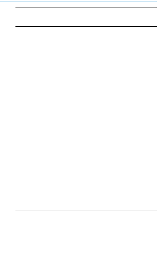
The following table describes the InTouch HMI documentation
library, delivered as PDFs. Online help is available from each
application.
Publication Name
(file name) Description
The InTouch HMI
Application Management
and Extension Guide
(ITAppManagement.pdf)
Describes how to create and
manage InTouch HMI applications
locally and in a network
environment. It also covers
application-level functionality, such
as security. This guide describes
how to run an InTouch HMI
application in different
environments, such as with Terminal
Services, on a Tablet PC, and using
multiple monitors.
The InTouch HMI Data
Management Guide
(ITDataManagement.pdf)
Describes how to work with data
items in the InTouch HMI and
connect your application to the
physical devices in your
plant environment.
The InTouch HMI
Visualization Guide
(ITVisualization.pdf)
Describes how to develop the
graphical operator interface of an
InTouch HMI application. This guide
includes information on how to
create visualization windows, how
to draw and animate graphic
elements, and how to use wizards
and ActiveX controls in your
application.
The InTouch HMI
SmartSymbols Guide
(ITSmartSymbols.pdf)
Describes how to create reusable
templates for graphic symbols that
can save you a lot of engineering
time and effort.
The InTouch HMI and
ArchestrA Integration
Guide
(ITAAIntegration.pdf)
Describes how to integrate the
InTouch HMI and ArchestrA
technology to develop more robust
applications that use richer
graphics.
9
For information on how to contact sales, customer training,
and technical support, see https://sw.aveva.com/contact.
The InTouch HMI Alarms
and Events Guide
(ITAlarmsandEvents.pdf)
Describes how to configure alarms
for your data items, how to view
and acknowledge alarms, and how
to use the alarm clients and utilities
supplied with the InTouch HMI.
The InTouch HMI
Scripting and Logic Guide
(ITScriptsandLogic.pdf)
Describes how to write scripts in the
InTouch HMI to automate
common tasks and processes. This
guide includes a reference of the
InTouch HMI scripting language
and functions.
Viewing InTouch
Application Graphics in a
Web Browser
(ITWebBrowser.pdf)
Describes how to configure and
view application graphics on an
HTML5 compatible web browser.
InTouch Access Anywhere
User Guide
(ITAA_UserManual.pdf)
Describes how to use InTouch
Access Anywhere to remotely
connect to your InTouch
applications by means of an HTML5
compatible web
browser.Administrator guides are
also available to help configure and
troubleshoot the ITAA features.
The InTouch HMI
Supplementary
Components Guide
(ITSupplementary.pdf)
Describes software components
that you can optionally install and
use with the InTouch HMI. You can
set up connectivity to SQL
databases, create data trends, and
manage industrial recipes. The
supplementary components also
include a library of symbols such as
meters, valves, and pumps.
Publication Name
(file name) Description

10 Getting More Information

